Broken Tumble Generator Valve (TGV)
FB25FB25BoutbackP2004P2007SubaruTGVtumble generator
2193 words. Read time: 9 Minutes, 58 Seconds
2023-09-24 21:25 +0000
Note: this is specific to the Subaru FB25B engine (2011-18 Forester and 2013-19 Legacy + Outback). If you have something else, this will probably be similar, but not exact. The successor is the FB25D, still used today with higher compression and direct injection. I have no idea how the heads and intake geometry have changed.
Since publishing this originally, my passenger side TGV has failed again. Oringinally I had the problem mid-August 2023 at 139,000 miles, the failure re-presented itself mid-July 2025 at 161,000 miles. So the fix lasted ~2 years and 20,000 miles. Not terrible, not great. Updates to this post will be marked with this style.
Subaru sells just the electric motor and worm gear (one part, just describing the mechanism) that drive the valve itself. They may have sold it initially too, and I just missed that important fact. Or maybe the part truly didn’t exist back then. Either way, it is now the option that I’ve become aware of and chosen to implement.
The problem
The other day on the way home my check engine light came on a block away from the gas pump. I was able to limp home. But I was a little concerned given that my CEL was on, parking brake indicator was flashing, and cruise control indicator was flashing. I also had a bit of a rattle when at lower RPM trying to accelerate. Being on the road already and about to be late for a meeting at work, all I could figure at the time was that maybe I was having issues with a CV joint, or maybe a tone ring had a broken tooth on one wheel. If I maintained speed at a lower gear, the rattle went away with higher RPMs.
 CEL - solid. Brake - fast blink. Cruise control - slow blink. The low framerate makes it look like the brake indicator is some sort of pattern, but it’s normal on-off-on-off.
After getting home I found two codes in my ECM; P2004 - intake manifold runner control stuck open, bank 1 (historic) and P2007 - intake manifold runner control stuck closed, bank 2 (pending). Before this experience, I had no idea what an IMRC, or what Subaru calls a “Tumble Generator Valve”, even was.

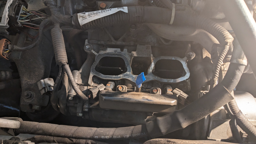
Why do I need a TGV? During a cold start the fuel has a harder time atomizing due to the lower temperature and low mass flow rate at idle. So when you start the engine cold the TGV will be closed. In the photo below, on the FB25 engine, the valve would close towards the inside of the engine, and air would flow through the bypass on the outer wall.
This lower cross sectional area should increase the velocity of what air is allowed into the head, and the abrupt increase in cross sectional area behind the valve should cause swirl. This is supposed to create turbulent flow, mix the fuel into the air more efficiently, and decrease emissions. Once your engine warms up, my understanding is that the TGV opens completely (straight up and down on the FB25) and remains that way until your next cold start.
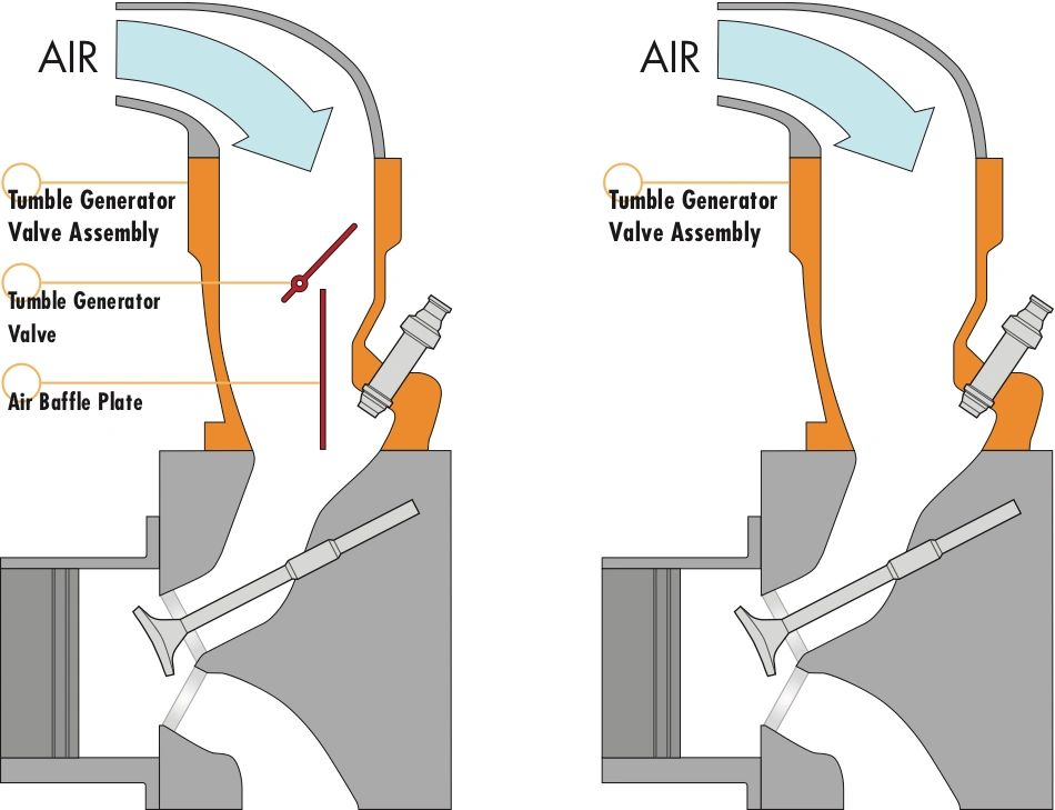 Illustration courtesy of AVO Turboworld
What was wrong with my TGV? Nothing, from what I can tell. It had built up its fair share of carbon from the EGR/PCV just like everything else downstream. I removed and tested both valve bodies. One worked fine and the other wouldn’t move. I cleaned it up a bit with carb/choke cleaner, a toothbrush, and some paint thinner and it all worked great.
After the second failure, the motor no longer shows that it has continuity on the two (bottom) pins of the connector that terminate the coil in the electric motor. I had briefly connected it to 12V DC to troubleshoot initially. And during cold starts, while waiting for parts to show up, I used some test leads to do the same as needed to open the valve in parking lots. I hadn’t actually tested the applied voltage the car supplies, so maybe I’m the one who burned it out. Or maybe it went on its own.
 Driver side, mostly closed
 Passenger side, open
The fix
Ok, so you want to get at your TGV(s) on your FB25B engine. How do we actually do this? The service manual is actually pretty accurate, if you have a copy.
-
Get the car into somewhere where you can keep it clean. This will probably take a full day if you’re doing it for the first time. It took me ~10 hours. (Including valve cover gaskets “since I was already in there…”)
-
Relieve pressure from your fuel system. You will have to disconnect the input and return of the fuel rails. You do NOT want 50psi gasoline spraying into your eyes.
-
Remove your glove box
-
Remove the entire glove box surround, along with long skinny trim piece on top, and triangular trim against the passenger door.
-
Unclip the 5x relays from the side of the electrical box
-
Remove the fuel pump relay, the bottom one
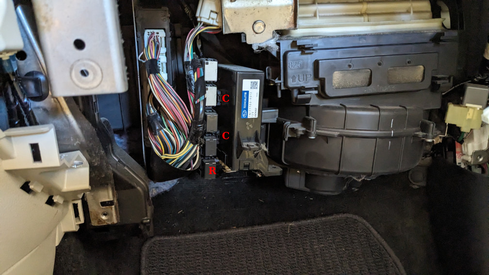 Clips (C) to remove the block of 5x relays. Fuel pump relay (R) on bottom.
-
Turn on the car and run it until it dies. Try to start it once or twice more to make sure you got it as evacuated as you can
-
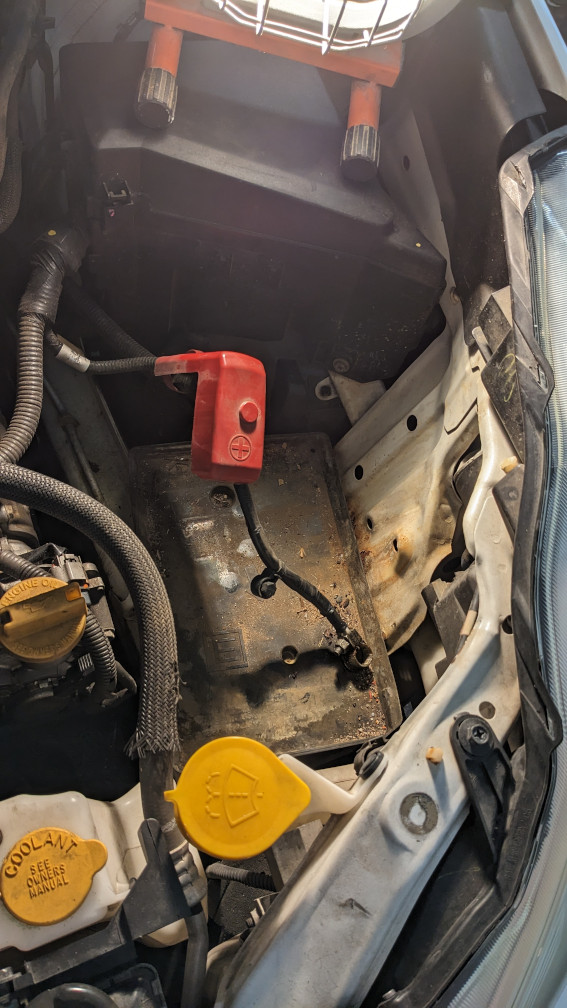
Remove the negative battery terminal. I preferred to remove the entire battery to have more room.
-
Remove the intake duct and resonator. I preferred to remove the entire intake to have more room.
-
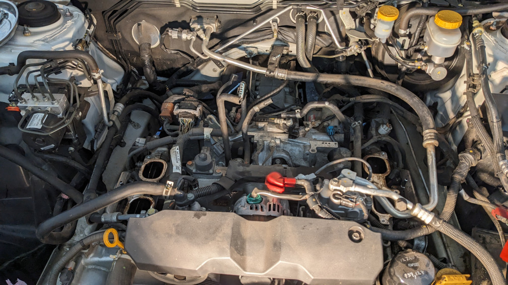
Remove the intake plenum
-
Loosen hose clamps and hoses from the throttle body
-
Remove the steel u-shaped tube below the throttle body (unsure if it’s PCV or EGR)
-
Remove 2x bolts on each of the runners
-
Lift the plenum up slightly. The PCV/EGR tube curves upwards after entering the bottom of the plenum, so rotating the plenum backwards should allow you to slide it over that protrusion. You can remove two additional bolts on the bottom of that tube, where it exits the block, but those nuts are very hard to get back on without small hands and lots of extensions.
-
Now that you can get underneath the plenum, unclip the feed and return lines using a pick. Also disconnect them from the short fuel rail on each bank.
I would recommend removing the throttle body on a bench, and cleaning out the intake plenum (remove the MAP/etc. first). But this is optional.
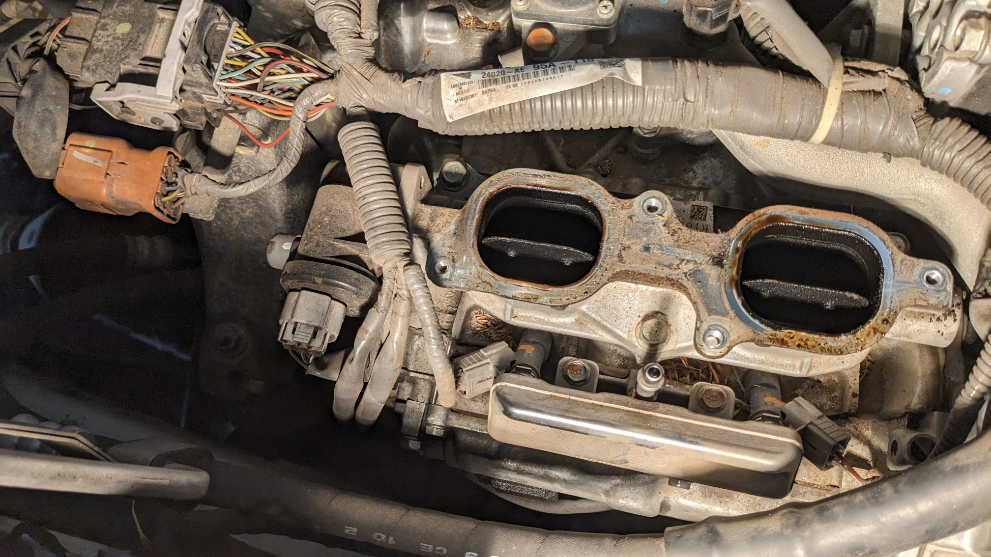
- Remove the TGVs. There are only three bolts on each holding them to the head.
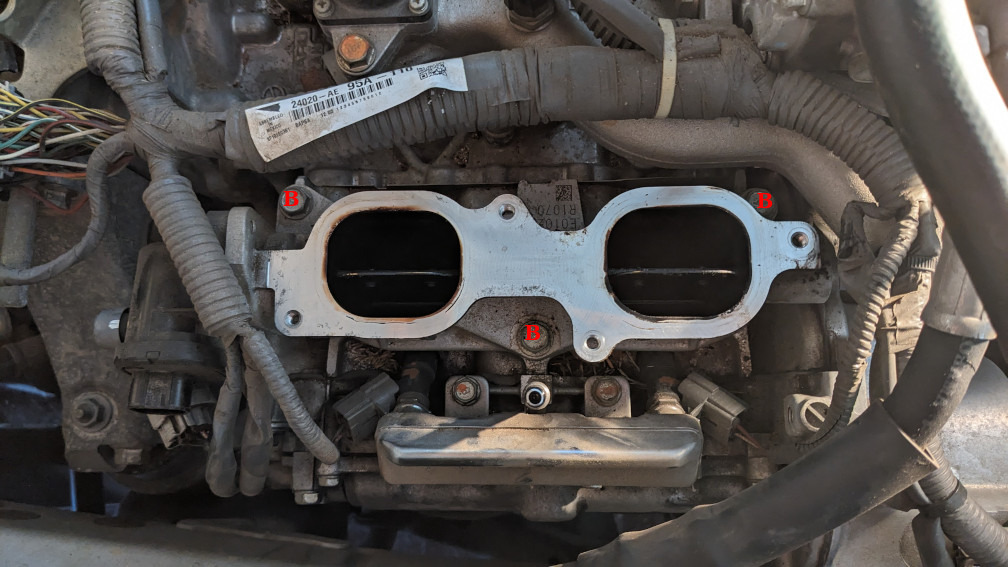 Three bolts (B) required to remove each TGV assembly
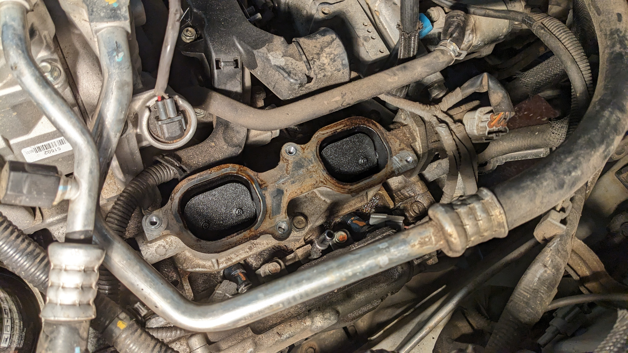
- Remove the gasket from the head, and block them off to prevent debris from falling in while working. I used carb and choke cleaner on a shop towel, wiping gently from the port to the outside edge of the head. Once complete, I covered them with some painter’s tape.
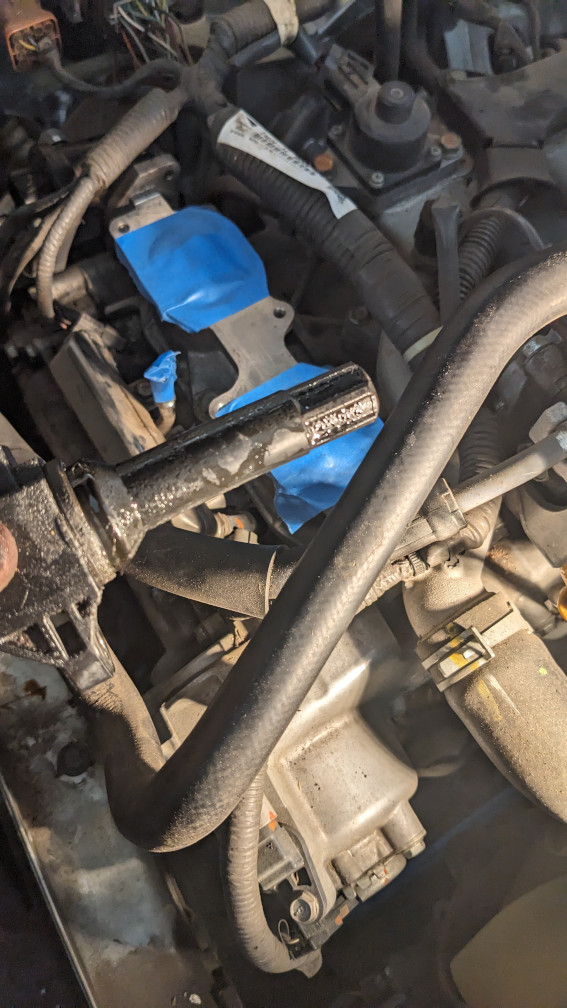 This was a photo to show how much oil had leaked past the spark plug tube gasket onto the coil boot. But you can see how the intake holes are covered in tape to prevent debris from falling in.
- Test the TGVs
- The service manual has the pinout for the connectors. Picture to be added, but there are 5 pins. 3 on the top row, 2 on the bottom. They are centered horizontally, so they’re in a W configuration. The pins on the bottom are 4 and 5, and drive the motor.
- Hook up some alligator clips (or female spade connectors if you have some small enough) to each. Make sure you’ve got insulation and aren’t shorting against other pins. Warning - You are only supposed to apply voltage to the motor for 10 seconds or less, or you risk burning up the windings.
- Apply 12V DC across the pins. It will either move or stay where it is, depending on polarity and starting position.
- Reverse the polarity, the vanes should move 90 degrees.
- Reverse the polarity again for good measure (if there was no movement the first time), it should move again, back to the starting orientation.
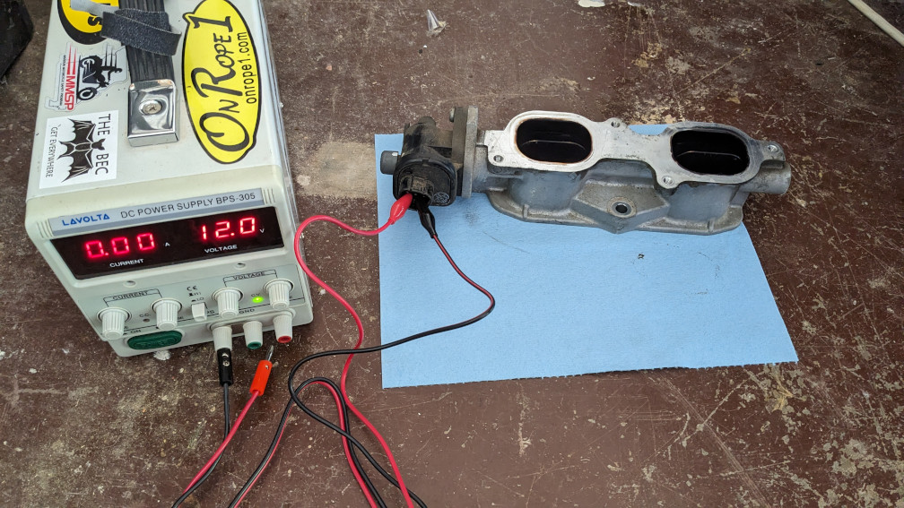 Alligator clips connected to two pins on bottom. It doesn’t matter what polarity you start with, as long as you don’t leave it connected for too long. We’re switching polarity with the banana plugs, since it’s easier.
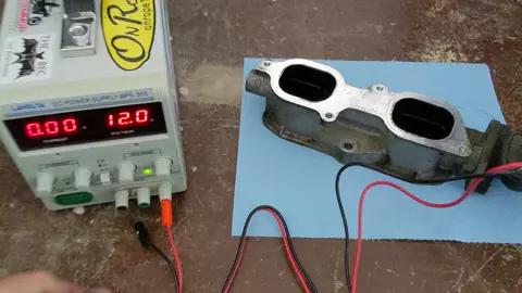 This is the good one. This is what it should do as you reverse polarities twice.
(optional) Remove the servo motor if it’s locked up.
- I set mine on a wooden workbench and used a wood clamp (with rubber pads to avoid digging into the aluminum) to hold it down.
- Use a phillips #3 (bigger than normal) screwdriver to remove the two screws. Keep lots of pressure on them, they are torqued well.
- There is nothing further in that looks serviceable. No springs/pins/etc. that would fall out
Installation is the opposite order of teardown. I took this opportunity to replace the valve cover gasket and spark plug tube gaskets since I’m already in here and they’re a problem. But I won’t cover that here since it’s a pretty well documented process.
 The inlet for this portion of the fuel rail has also been covered up with tape, since all of the filters are upstream from here.
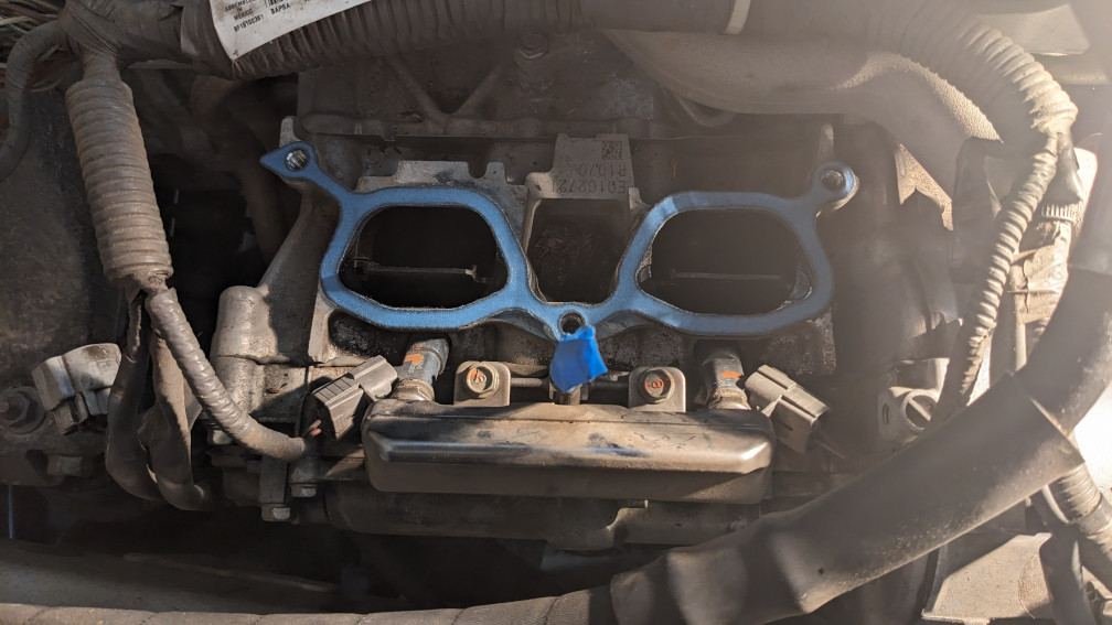 Replacement gasket in place, ready to install one TGV. Make sure to orient correctly, you can put them on backwards. But left and right are the same shape.
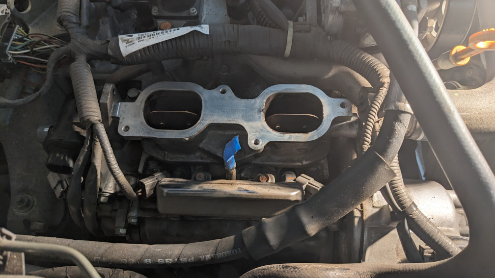 Clean(ish) TGV reinstalled.
Replacing the motors only
This part of the procedure can be used if you don’t want/need to clean the valve itself, and you only want to replace the electric motor that hangs off the end of the TGV assembly.
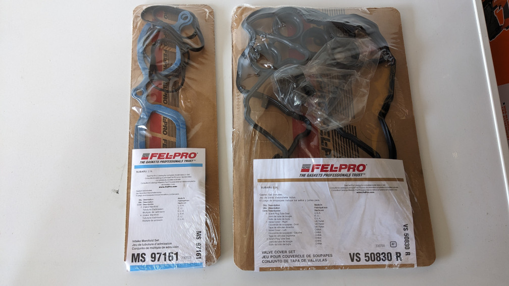
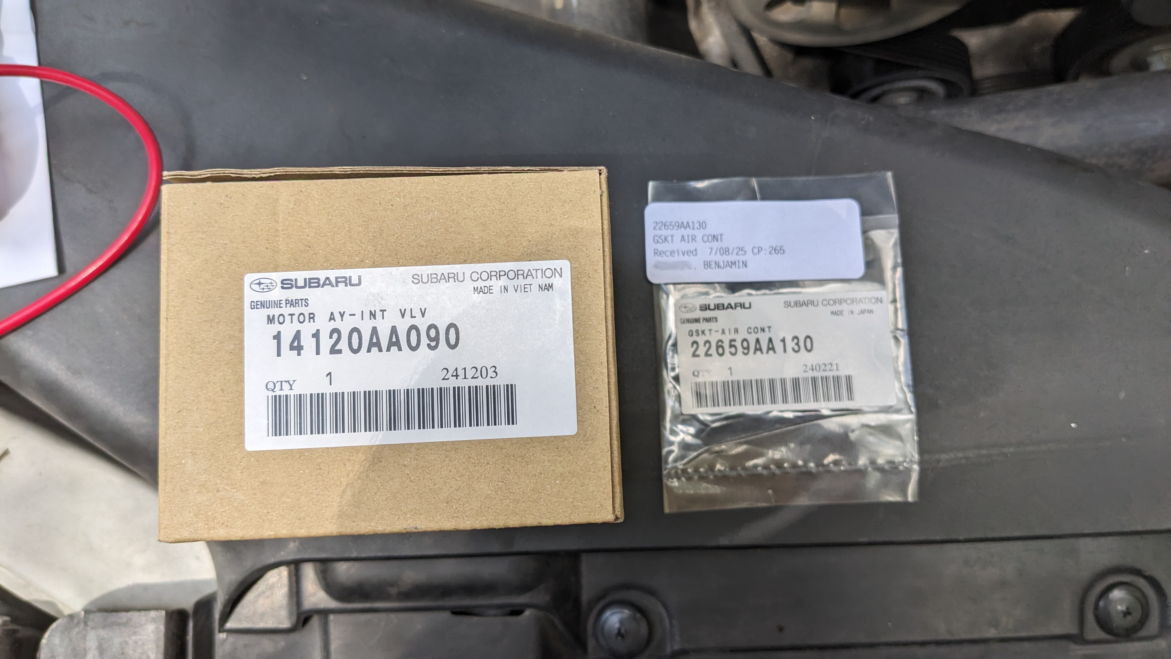 These are the part numbers for both the motor and the seal.
-
Remove the electric motor from the TGV assembly. This will require a Japanese Industrial Standard (JIS) #2 or #3 screwdriver. It looks similar to phillips, but has a slightly different profile. A phillips #3 has a decent chance of not stripping out the screw, but JIS seems to work better.
-
Unplug the connector from the electric motor assembly.
-
(optional) Remove items in the way of the screws. On the passenger side, I removed the intake and resonator (just the tube between the air filter and buterfly valve), unplugged two connectors of the wiring harness, and the bracket that holds said harness connectors. Alternatively you could use a stubby screwdriver, or a right angle driver.
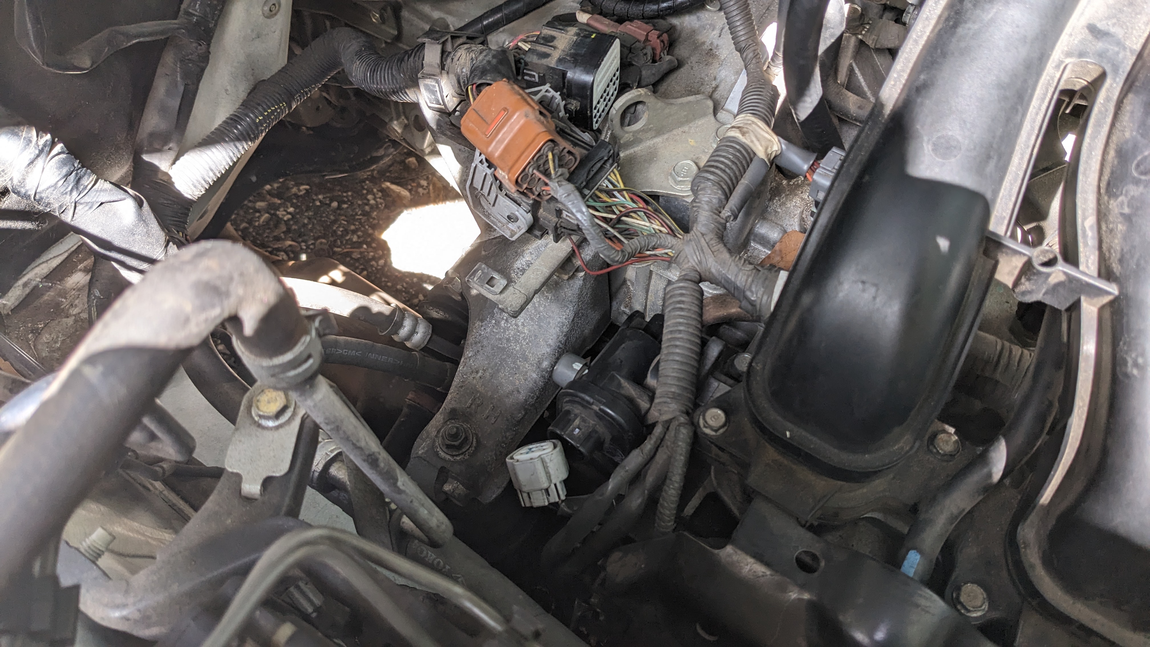 These two connectors on the passenger side need to come out. The orange one is clipped on, and can be removed with a pick or small flathead.
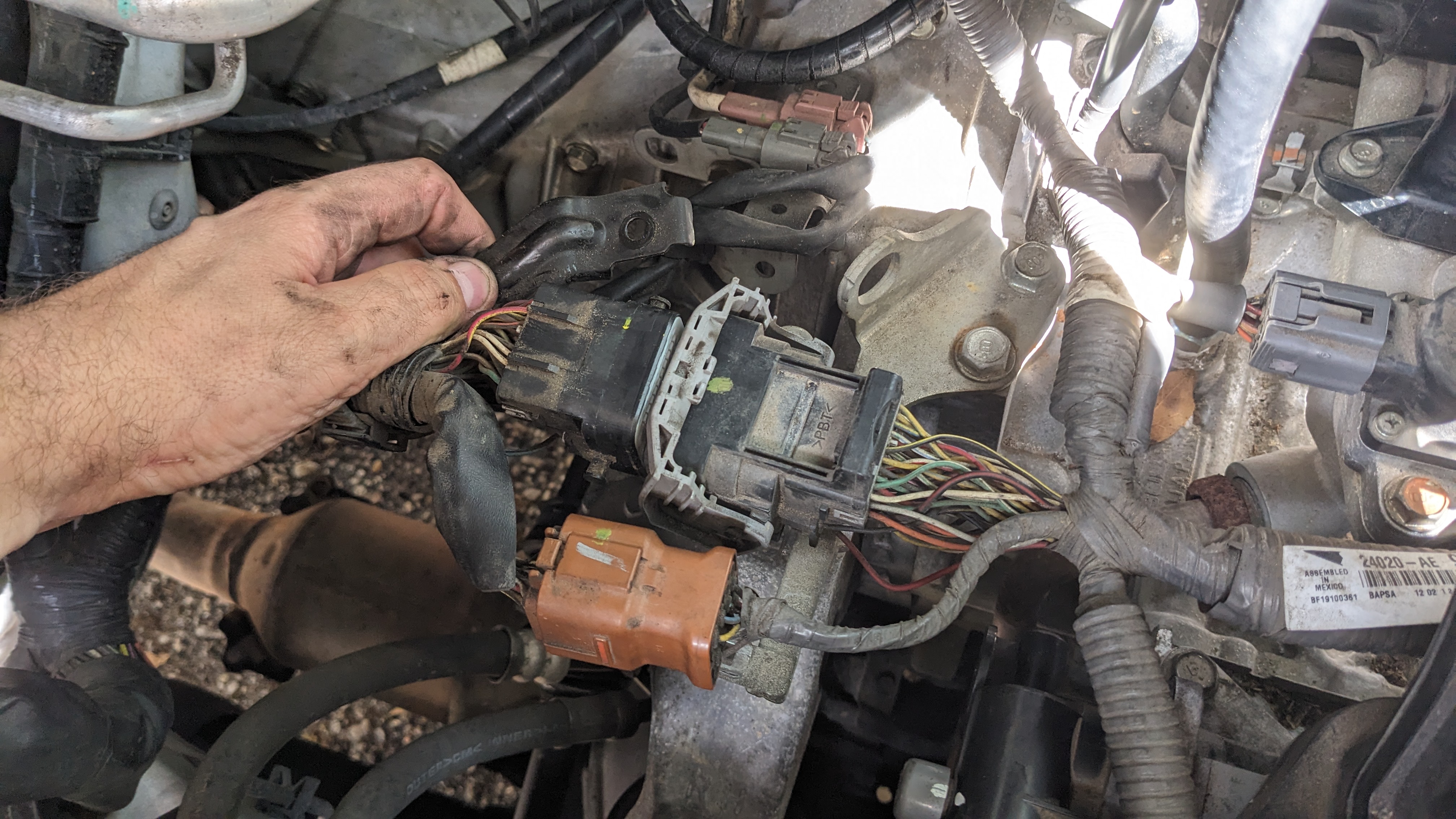 This metal bracket can be removed, and the larger grey connector pushed out of the way.
- Loosen the two screws. You will need to keep a good amount of pressure, even with a JIS bit, to keep the bit from camming out of the screw head. An impact driver isn’t necessary. But you may want to put a wrench onto the screwdriver handle to help turn, and just push with the other hand.
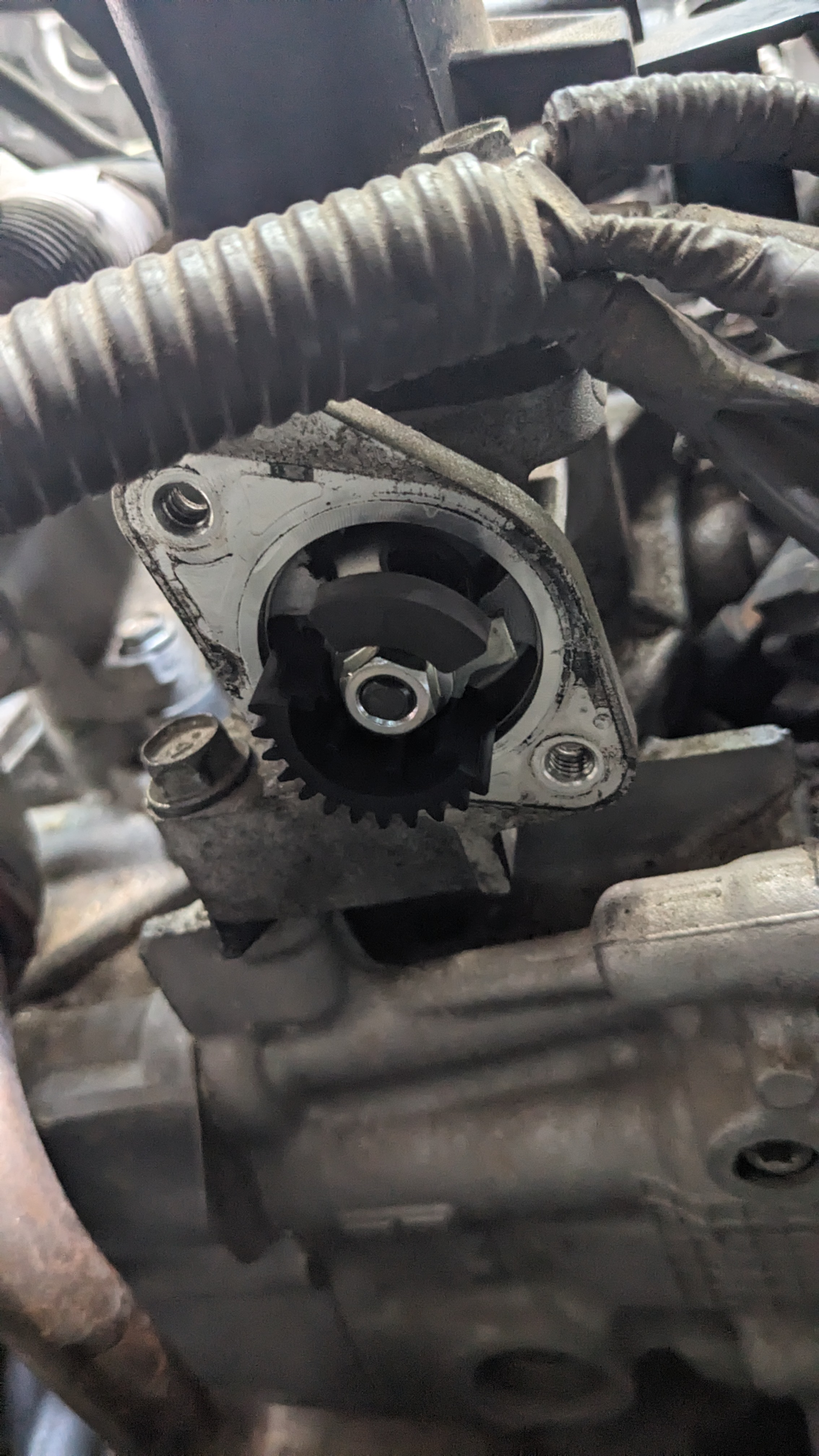 The two screws are here. You can inspect the valve motion by just rotating by hand. No disassembly of the intake plenum required. It should rotate smoothly.
-
Remove the electric motor. There is a square profile o-ring between it and the TGV housing. My seal was stuck to the TGV housing and needed to be scraped off with a fingernail. It could have been reused, but I bought a spare for a few bucks.
-
Reuse the old seal, or install the new one into the groove on the face of the new electric motor.
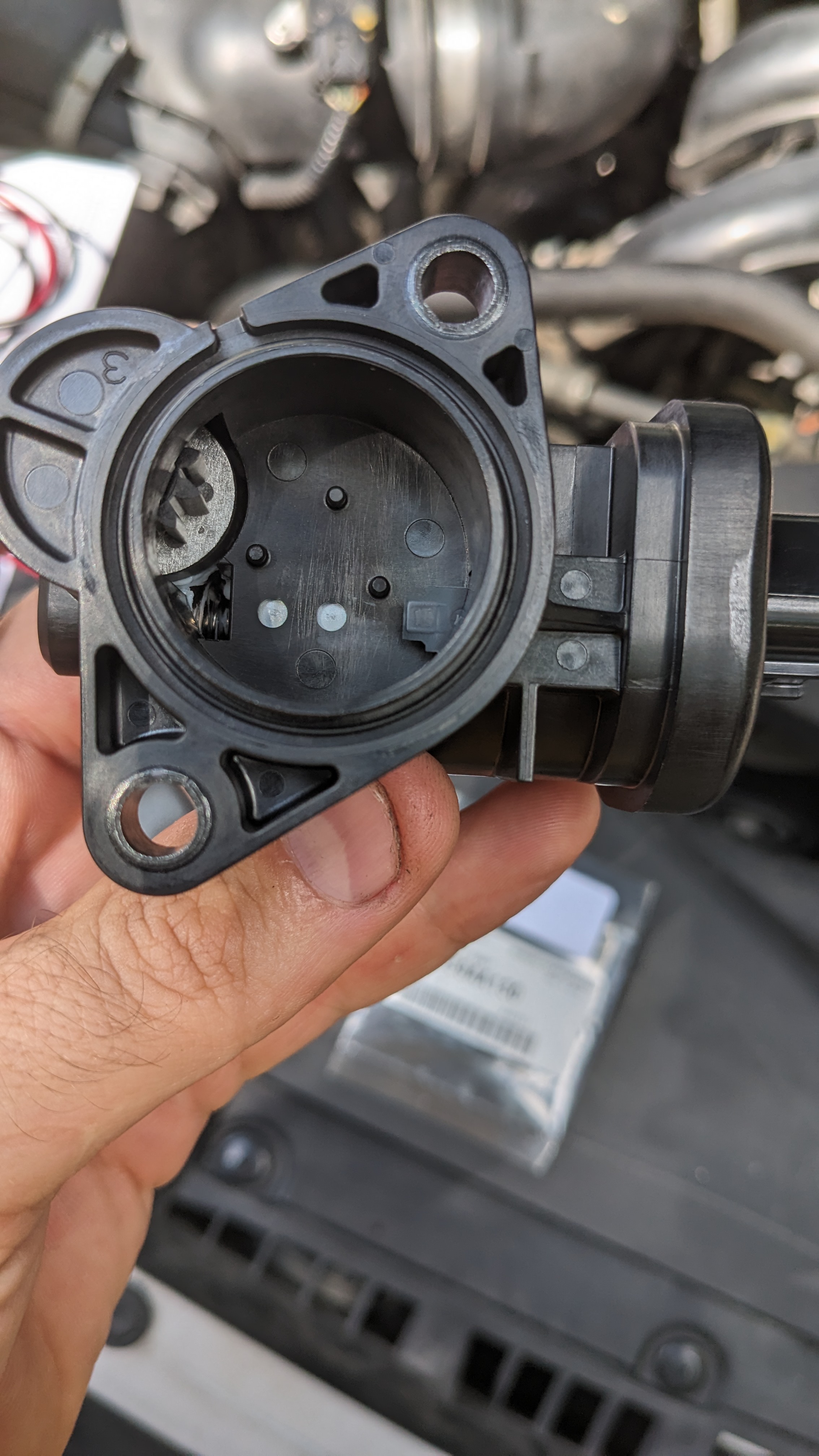 Where the square profile o-ring lives.
- Assembly is the reverse of disassembly.
Note: The motor is “dumb”. Simply a brushed DC motor with end stops, not a stepper or servo. It just runs for a set amount of time in the chosen direction. If you re-assemble with the valve open/closed mismatched with where it was when you started, it won’t ruin anything.
- On first startup, the PCM should ensure the valves are rotated into the appropriate open/closed position. If not, you can just read and clear the codes with key-on engine-off, and everything should be fine on the next startup.
Closing comments
At this point I’m 2 months late posting this. But I’ve had no issues with any part of my intake since the fix. If anything stops working again, I think the solution is going to be to buy a set of used TGVs from a wrecked car on ebay, then replace just the servos. This shouldn’t require removing the intake, just pushing some hoses and wires out of the way.
As mentioned at the top, these did fail again after ~20k miles. But Subaru sells just the electric motor and worm gear to drive the valve. Brand new, they cost me $190 from the parts counter at the dealership. If you get them elsewhere online, they can be had for cheaper, but I was willing to pay the premium to just have them show up at the dealership, which is like 3 miles from my house. Still much better than $700 or so for a new TGV assembly, or ebay/junkyard parts of questionable pedigree.