The girl has a bike. She likes to go mountain biking with the rest of us. She also doesn’t have a cage for a water bottle and wants one for christmas.
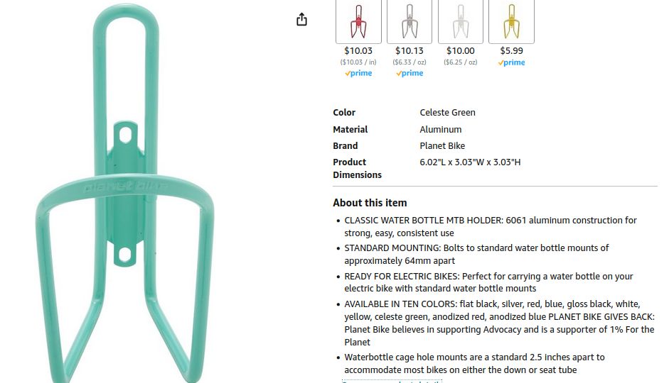 I appreciate them saying that it’s both 2.5" and approximately 64mm in the same block of text. Way to be equal opportunity with measurement systems Amazon!
But her bike for some reason doesn’t have mounting holes anywhere for accessories. This is what you get when you buy what’s available at the very beginning of COVID from Walmart…
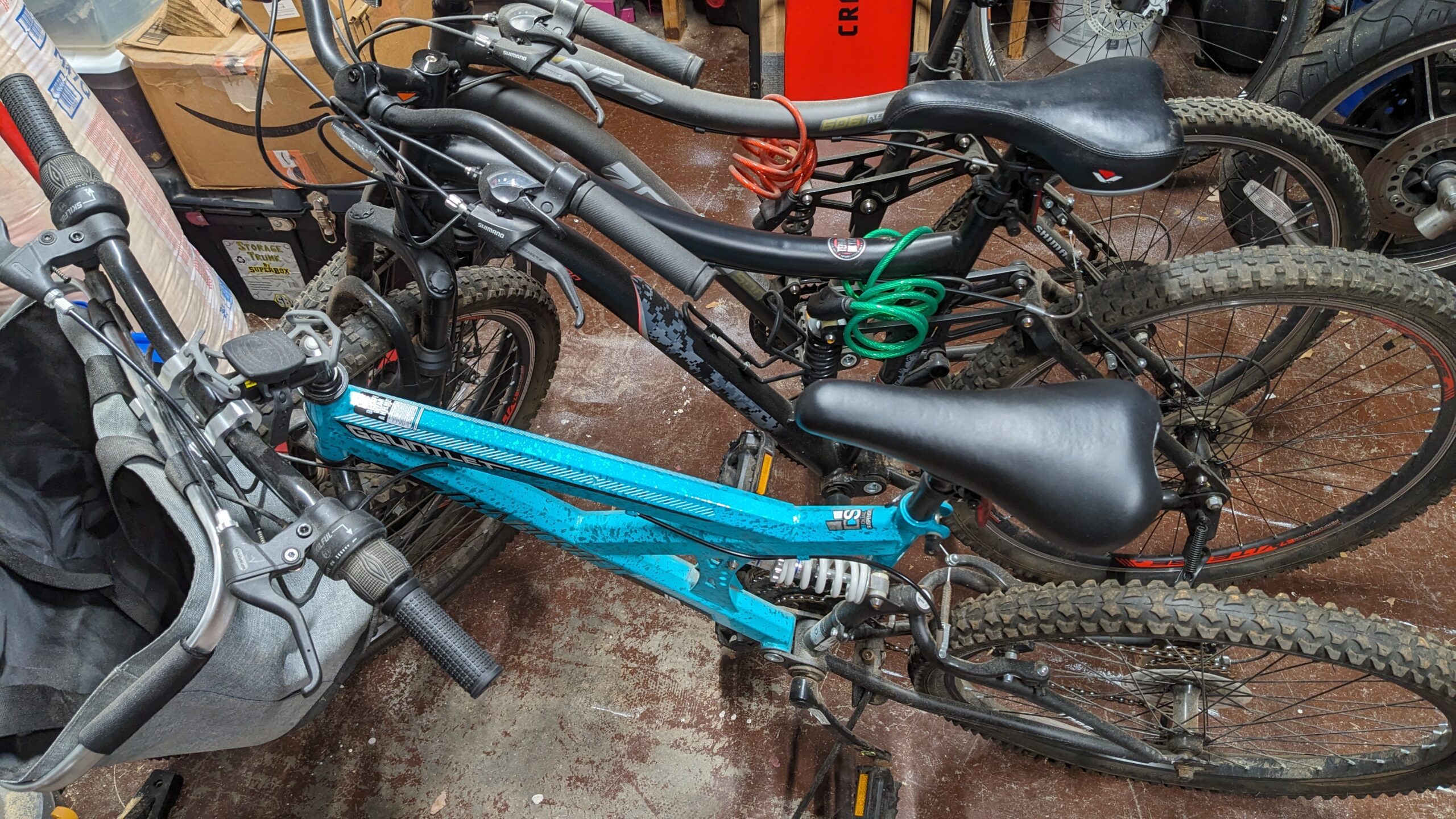

Almost every bike (not for kids <=6 years old anyways) has at least one.
Almost every moderately priced to expensive bike has two in my experience. I really wonder what two holes and nutserts would add to the overall cost of a single bike.
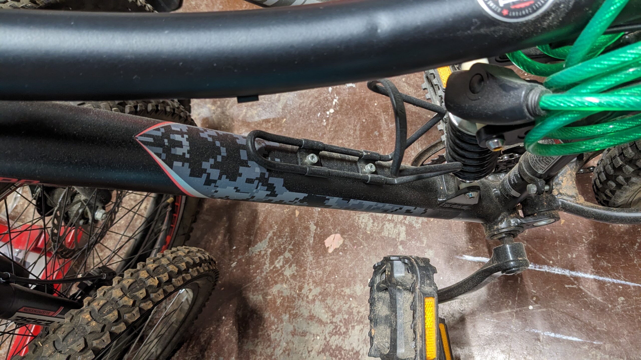
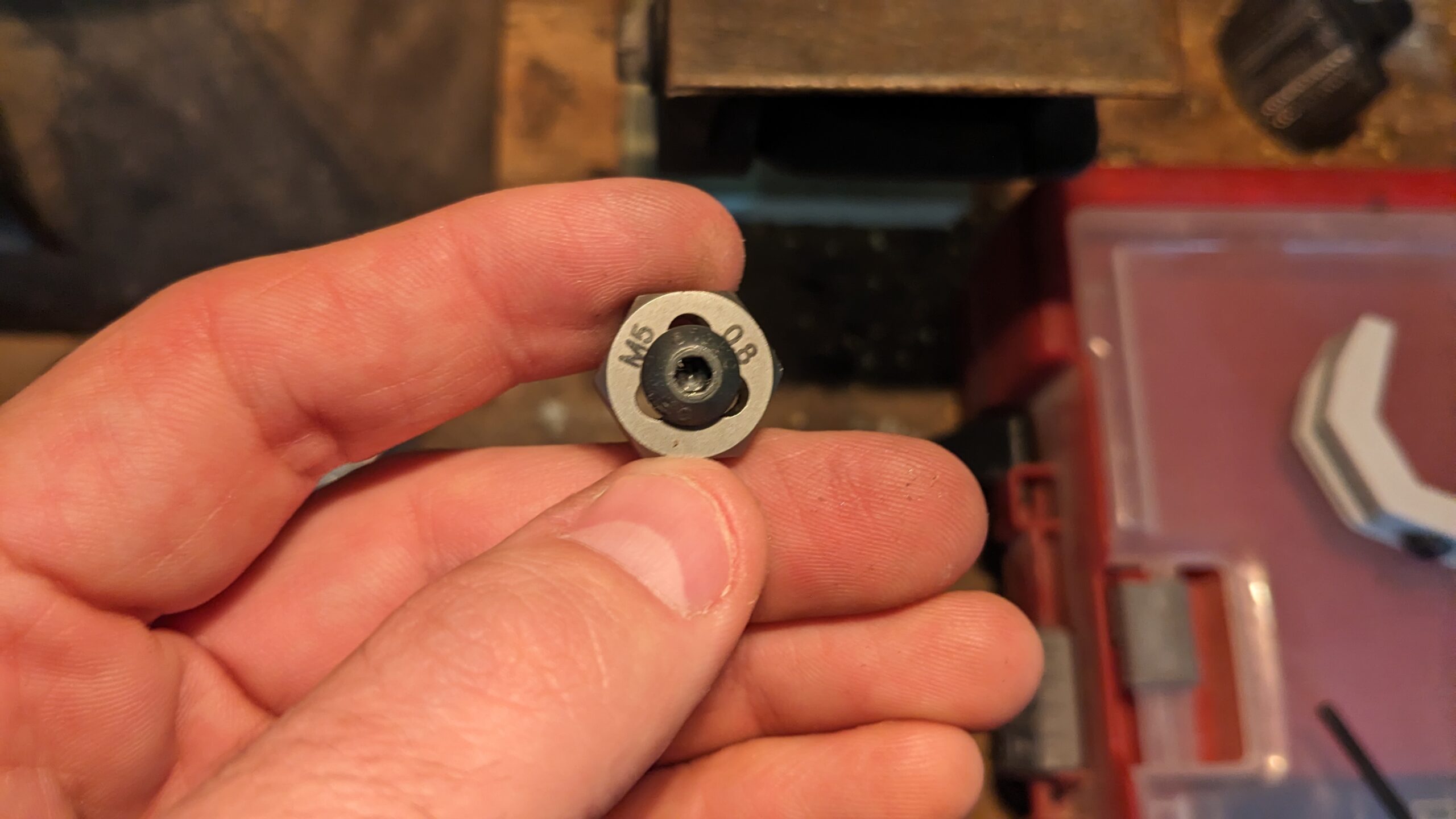
I have a 3D printer [of questionable quality], and Solidworks. So with a few screws and nuts (M5-0.8 is the standard for bikes) we can make something work. My first idea is to create a saddle what will hold some captive nuts, zip tie that to the bike frame, then have ridges on either side to keep the zip ties from wiggling off during use.
Zip ties will do most of the work. My design requirements are; there’s something to screw the cage into, the bottle won’t slide to the left or right (in the path of knees) when fully weighted, the cage won’t scratch up the bike’s paint, I don’t pinch the shifter/brake cable underneath the top tube.
Create a Draft:
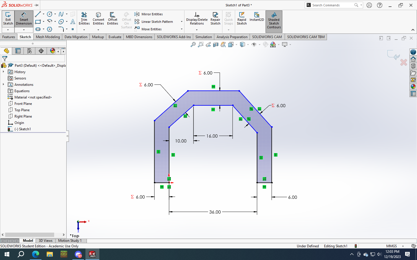
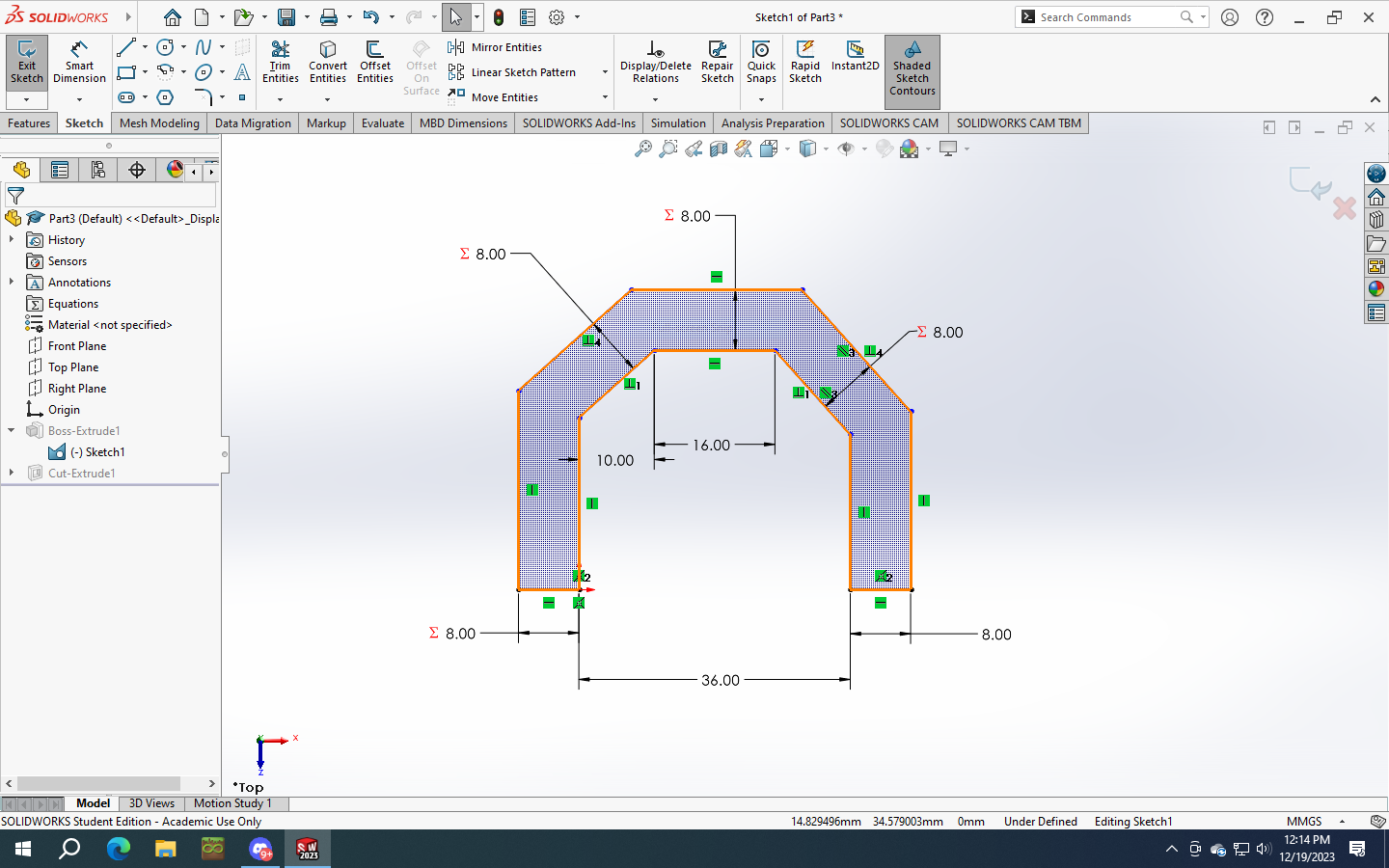
Create the polygon first, then dimension it, and extrude.
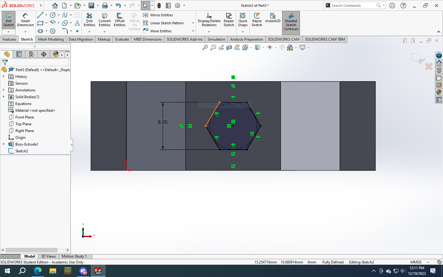
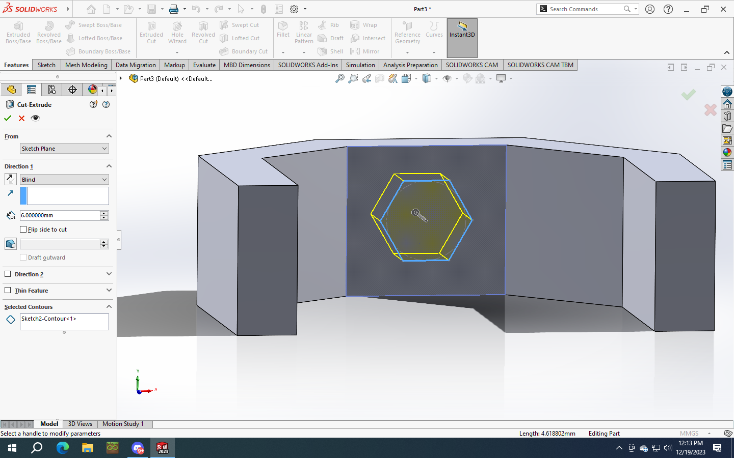
Then create a hole for our recessed nut. The interwebs says a M5-0.8 nut fits into an 8mm wrench. So I’ll create a hole exactly that size. If it’s too tight I can melt the nut into place with a soldering iron. And we’ll go 6mm deep, to make sure it doesn’t touch the bike frame when the zip ties are tight.
A tip for centering your polygon in the available space. Click on a line above, right click, and “select midpoint”. Then simultaneously select that midpoint and the center point of your polygon. You should now be able to create a vertical relationship. Do the same with a line to the right or left and create a horizontal relationship. In the image below you can see the vertical applied to the center point of the polygon, another vertical applied to a point on a reference line, and a center point applied to that reference line.
There are no good ways to snap the angle of the polygon to an existing reference that I know of offhand. So once complete, select one edge of the hexagon and either the top or bottom line of the main body, then create a parallel relationship. Finish with the blind hole cut to depth.
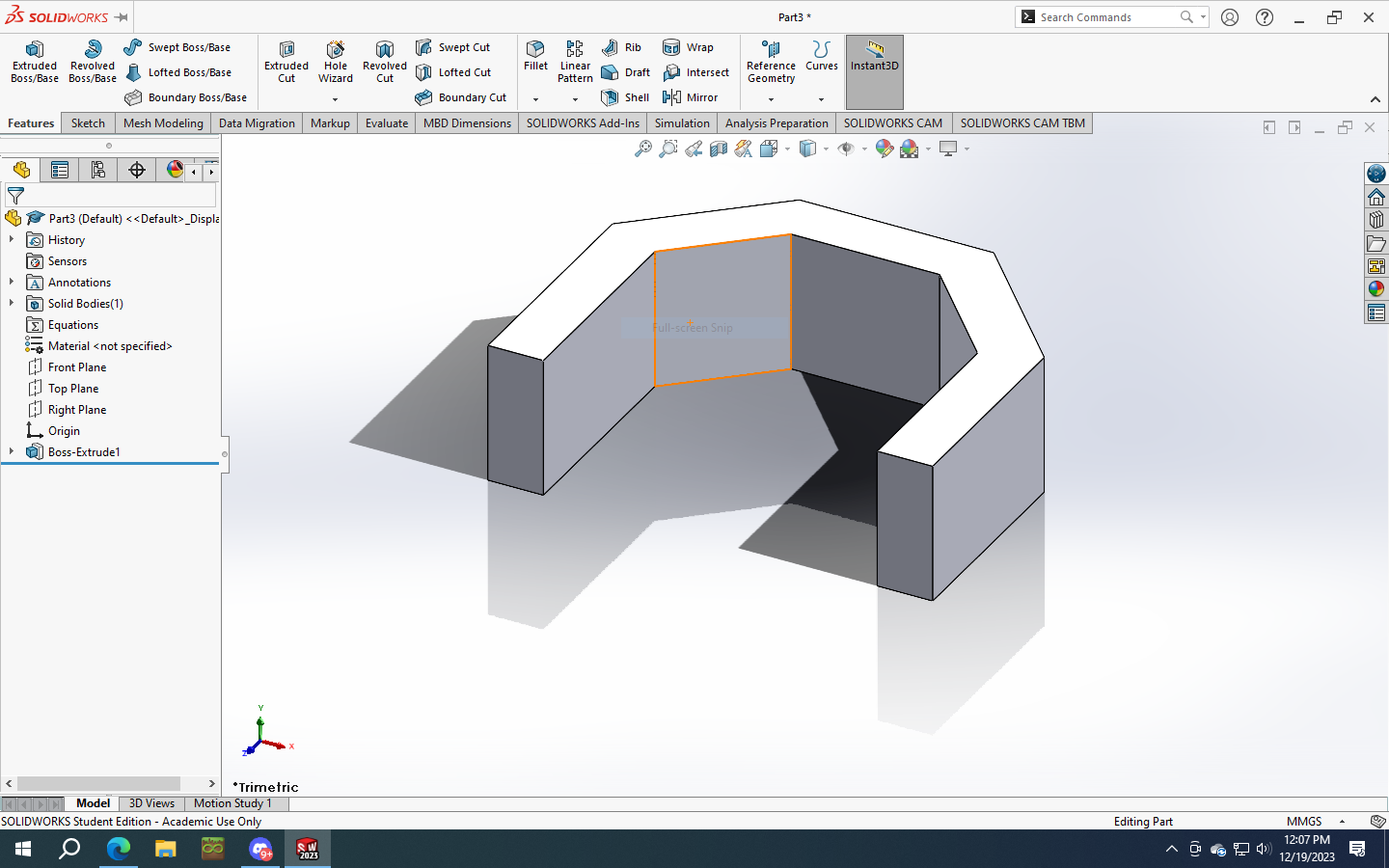
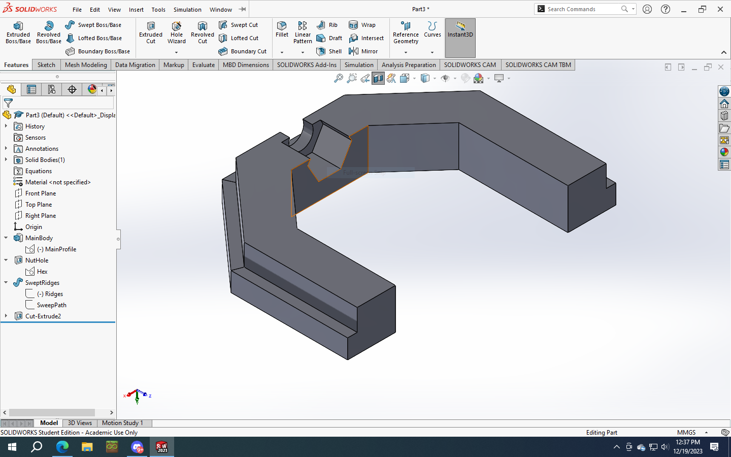
Next I’m planning to sweep ridges onto the main body to keep the zip tie from wiggling off either side. Create a new sketch on the main profile. Use the line tool to make a u-shape along the outer line of your main body, coincident with the existing points. Select all five segments, right click, “Sketch Tools”, “Make Path”. This will make one continuous line instead of one that’s disjointed. The swept base feature will get angry with a segmented line.
Now select one of the feet, I’ll call them, and create a new sketch with two rectangles. Make sure to draw them with corners coincident to existing corners, and the second one with vertical relationship to the first, which should pop up auto-magically as you draw, with a dotted line if you’re unfamiliar with SW.
The only dimensions you should have to add now are a thickness, 2mm here. Also a width, 4mm. Again, make sure to set one width, then subsequent ones use the existing one as a formula to save time when re-working the model.
Finally we’ll continue in the hex area with a 5.1mm through hole. This didn’t want to pick up the center axis of the hexagon, so you’ll have to use the “Select Midpoint” trick again to make sure it’s centered.
Print and Test Fit:
Halfway through the print I realized there were a few oversights that needed fixing. But I let it go to see if there were any print issues that needed to be corrected.
- The ridges, as printed, aren’t going to work well. I don’t have supports turned on, because I hate prying them off. It turned out ok, but I’m putting a chamfer on it anyways.
- The solid infill on the top layer is a bit under-extruded.
- The chamfer for the zip tie to get back close to the bike frame isn’t symmetrical, they’re using different planes as references for the depth/angle.
- The slot for the zip tie is wider than required. My zip ties are 4mm wide.
- The ridges for the zip tie are thicker than they need to be. The zip ties are only ~1.25mm thick.
- The pocket for the nut is deeper than it needs to be. I’d like a lower profile nut given the light load it’s carrying, and that allows more support on the top side to keep the nut from breaking through, without increasing the thickness of the main body.
- The 45 degree chamfers that touch the frame aren’t symmetrical. I thought the relationships I had would take care of it, but the part as it sits is under-defined. One fits really well, and the other has a gap with the bike frame.
Fixes:
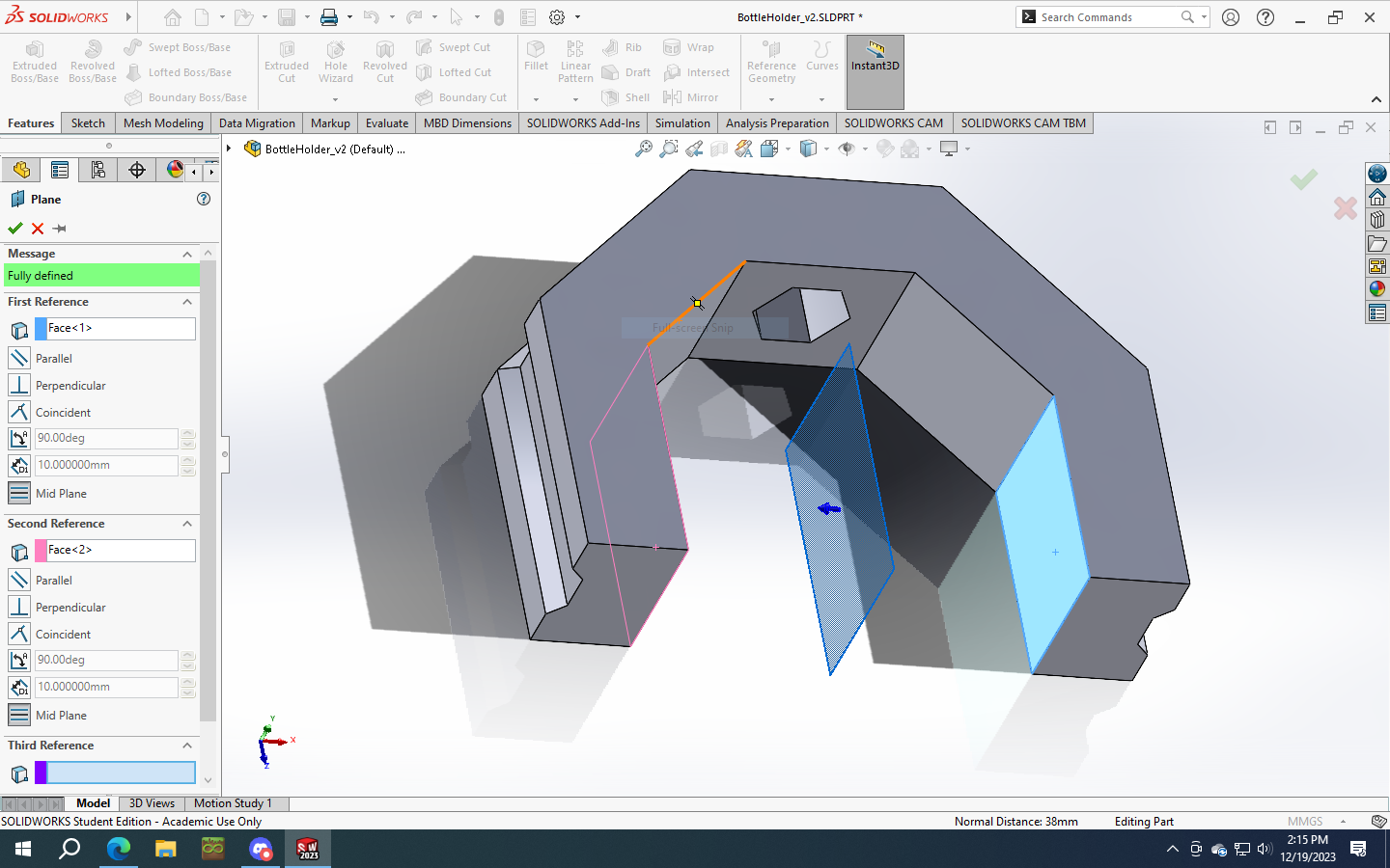
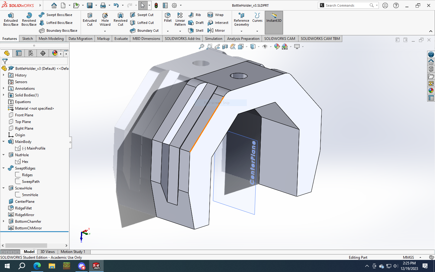
This time around I decided to mirror as many features as possible. After fixing the main profile and rebuilding, we “Create Reference Geometry”. “Plane”. Then select two parallel planes, and it will automatically guess that you want your reference plane equidistant from the two references.
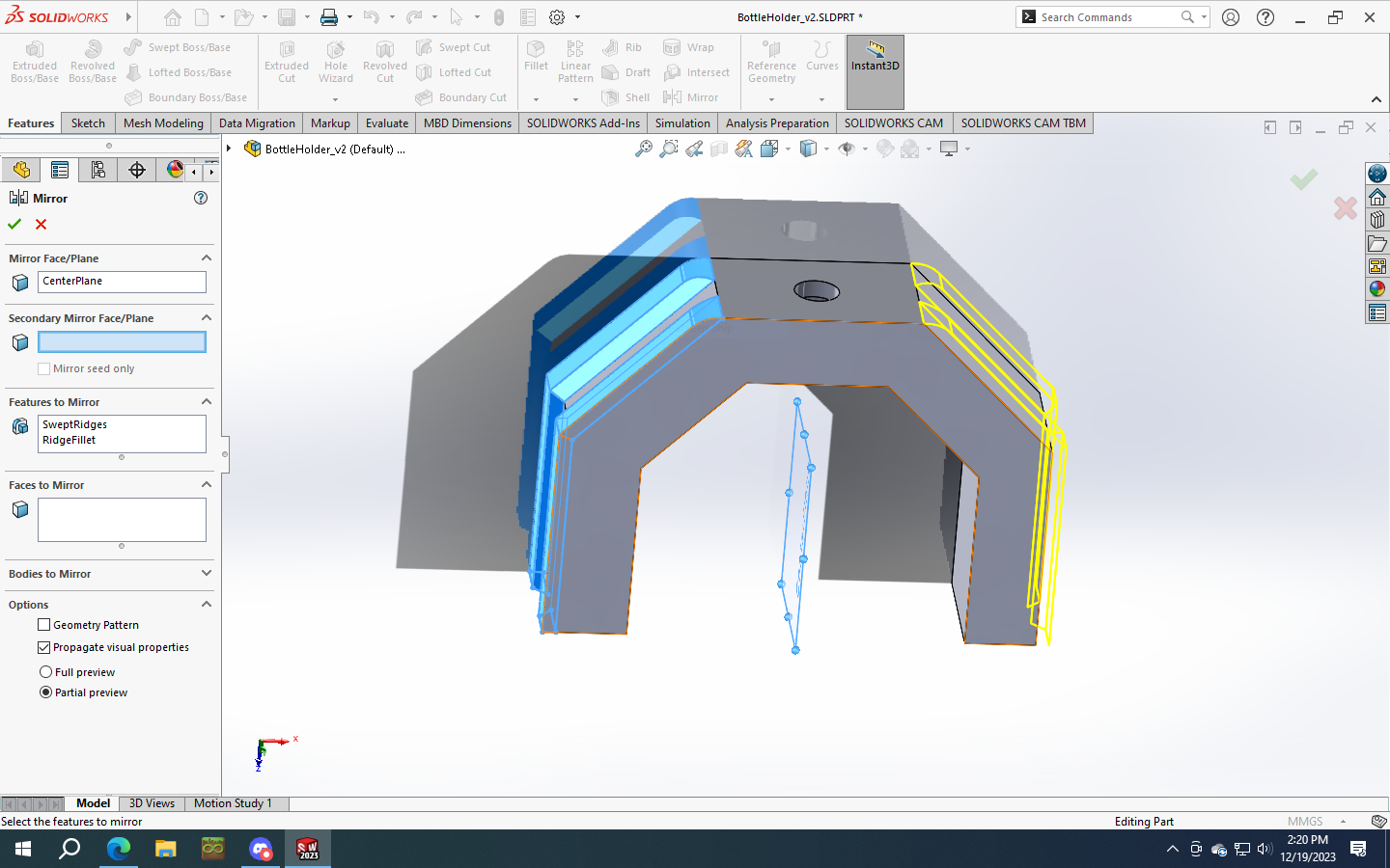
Next we’re going to our path, and deleting 3 out of 5 of the individual line segments. Exit the sketch to rebuild, and notice the small protrusions on top. This is because the swept profile follows perpendicular to the path. We’ll select both of the nubs and throw a 4mm fillet onto them to round them off nicely below the top plane of the part.
Select both the sweep, and the fillets, and mirror both features about the reference plane.
Now that the ridges are not rectangular, I can’t elegantly build the same chamfer into the bottom. The interface with the slope on each side will jack up the swept ridges if I start deleting pieces of what they’re built on. A fillet won’t work either. Instead I decided to lop off the corners at the very end.
Select a top plane of your main profile (front or back surface as it sits on the bike), draw a triangle for the portion you want to destroy, and save it. I believe this is a 20-70-90 triangle, 12mm on the longest side. Close the sketch and create your extruded cut. Then finish by mirroring it off of the same plane as before.
Save version 3, export as a .stl, slice it, and send to the printer. I’ll do just one to start with to make sure my print settings still work and not waste time/filament.
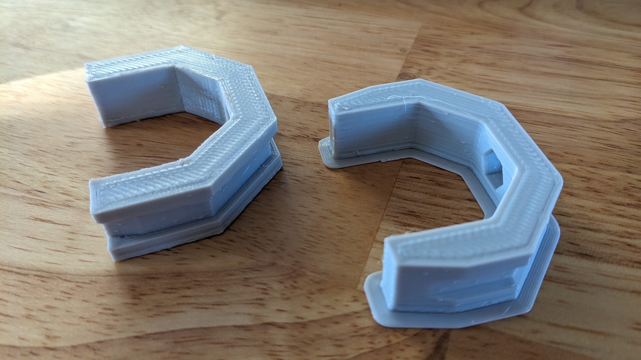 Left - original, right - new.
This is printed with some grey PLA from American Filament, because they’re local to Huntsville and I enjoy being able to actually drive to a store and pick up filament the same day that I decide to buy it. It seems to prefer 195°C extruder, 68°C glass bed, and 22°C enclosure. My z-offset is messed up recently and I’ve been too lazy to mess with it, so I’m babysitting the first layer at 250% flow, 75% feed, and no fan. Then let it run at normal feeds/speeds until the end.
I must say that this is one of the nicest prints that I’ve done in a while. I usually don’t care much about aesthetics, and am happy to hit things with sandpaper and a file. But when I’m giving it to someone as a gift I’m more inclined to take the time and dial in my settings. I think this has been ~10 small test prints over the last 2 days, and it definitely paid off getting the new filament dialed in.
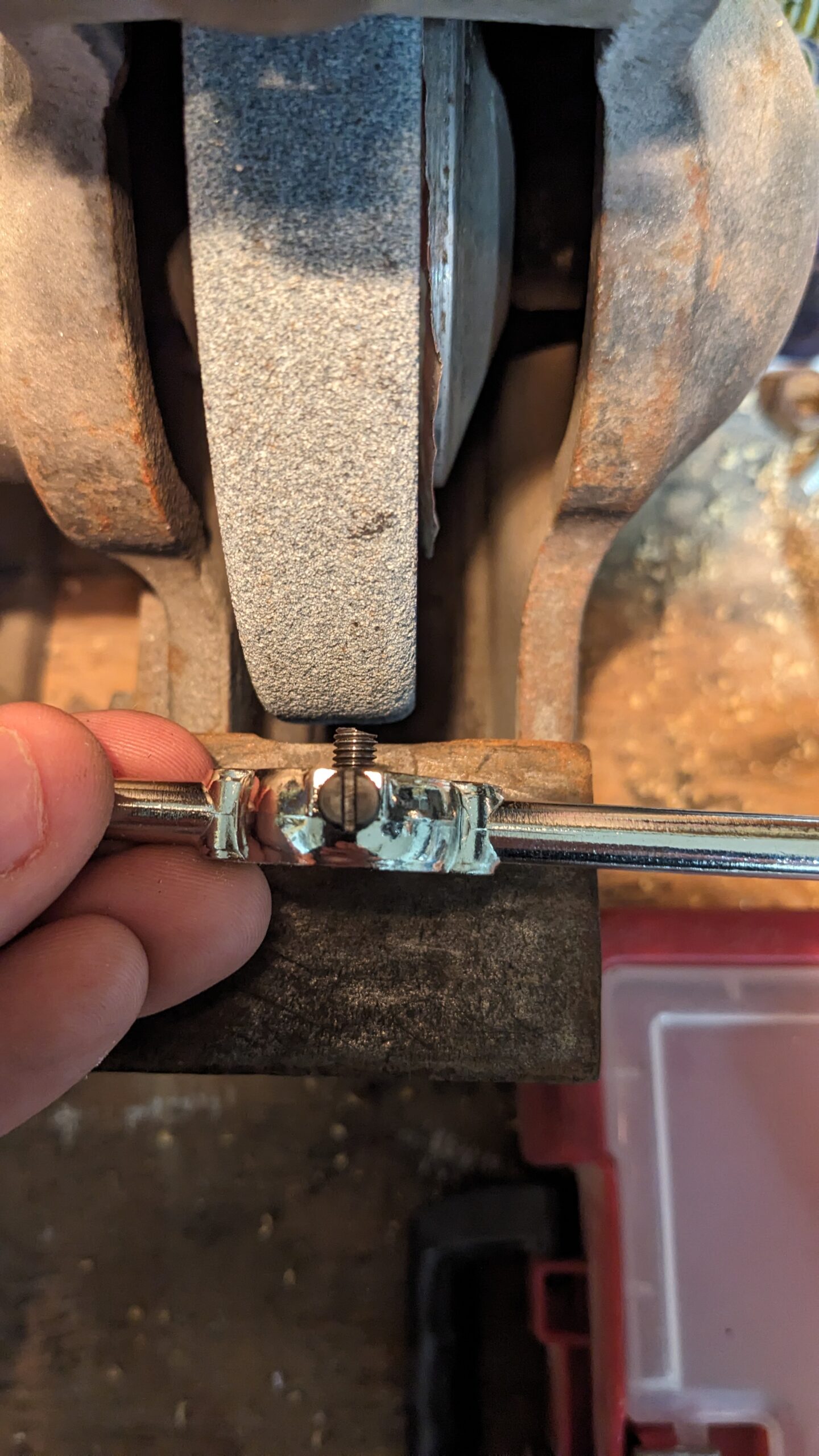
Still have a little bit of an elephant foot on each, which I’ll turn towards the interior (to reduce drag…). The machine screws I used ended up needing to be shaved down to about 9mm length. You could add a washer, or modify the part to be thicker to keep them from poking through the back into the bike frame. I chose to shave them down on the bench grinder.
 The nut will smooth the threads out also as you back it out, but the shape of this part isn’t conducive to grinding
Pro tip: Use a M5-0.8 die to help hold your screw up against the wheel easier, and when you run the die off of the screw it will straighten out your threads that got mashed on the end.
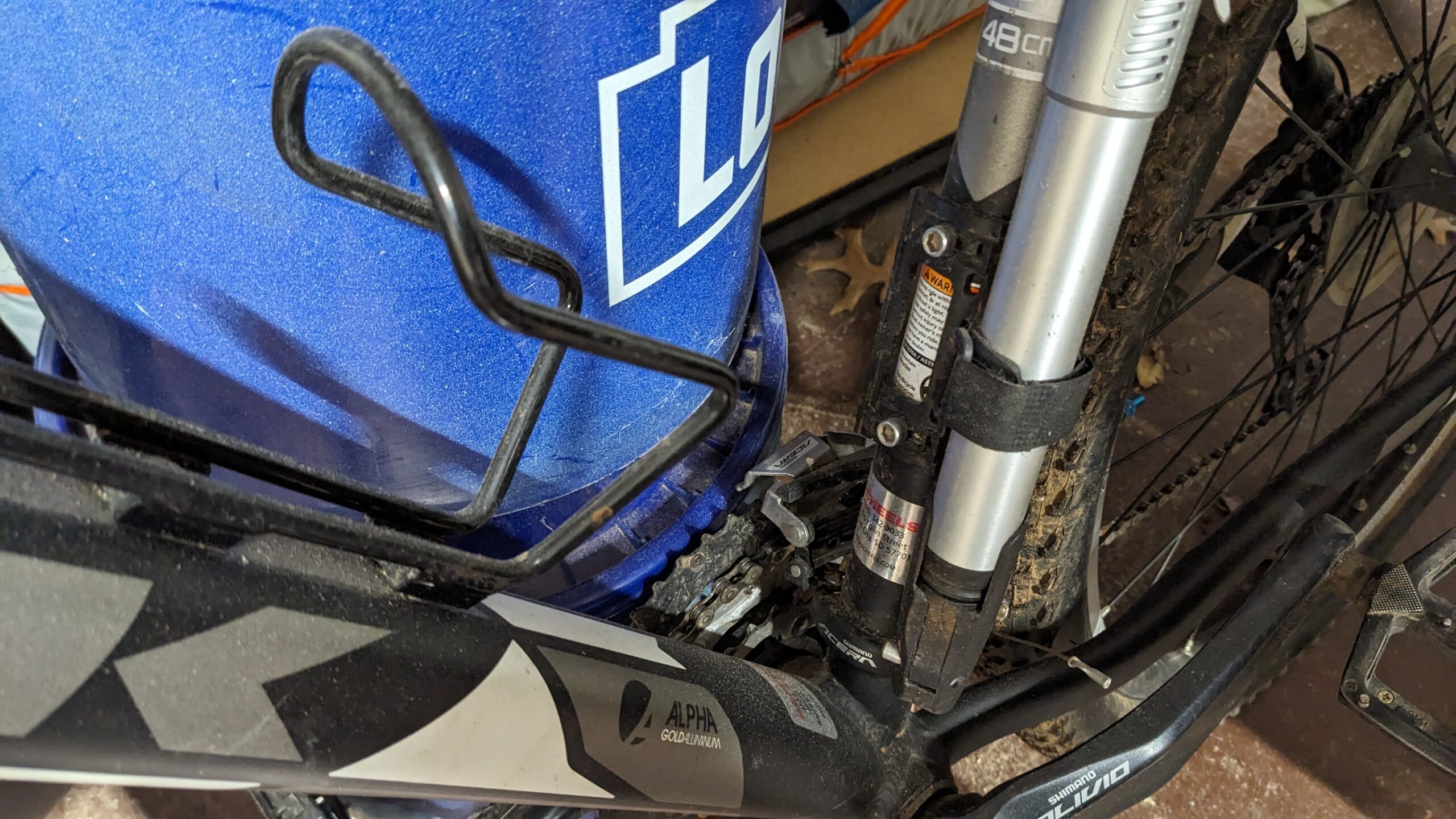
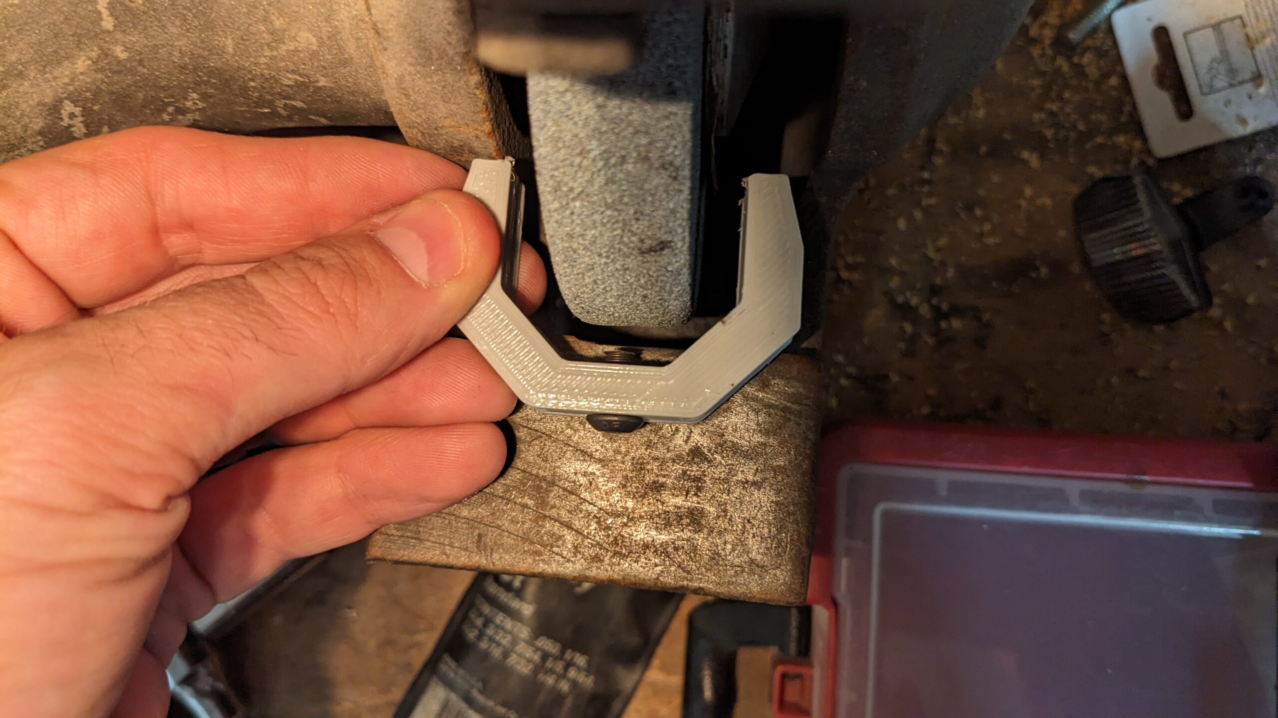
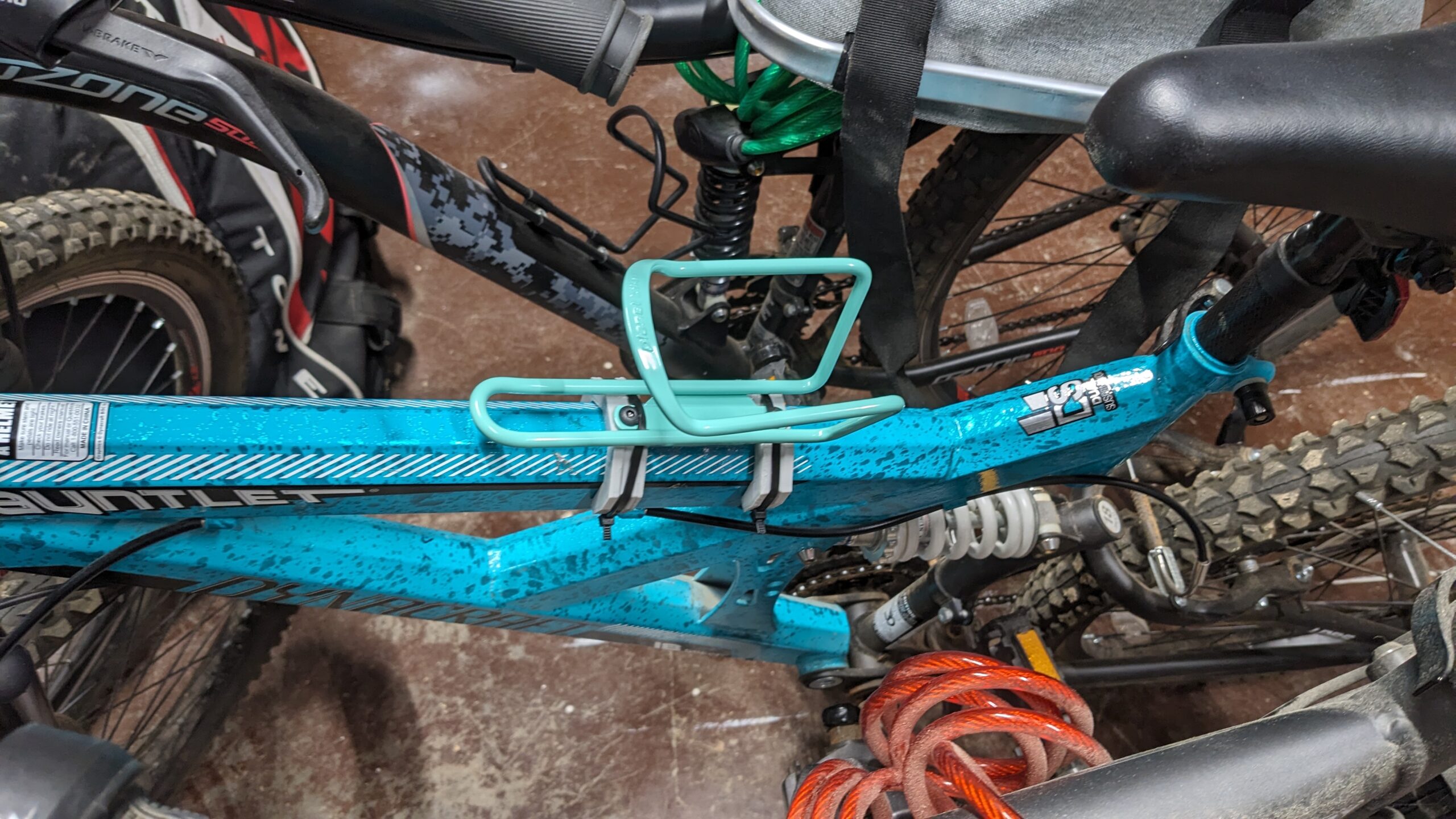 The final product. Slight interference between screw head and zip tie. But it’s surprisingly firm after pulling the zip ties tight with pliers. I’m not worried about it popping off during a ride.
And here are the original files so you can use/modify them yourself if you want. The .sldprt and .stl are both included in the single .zip file.