This is applicable to a Skutt KM1027 kiln. The KilnMaster series are all pretty similar, so this will probably work for many other models as well. But that’s specifically what I have.
This is also specific to electrical systems in the United States, because that’s where I am. The concepts will be the same anywhere, but you’ll have to do some of your own math in part 2 if you have different voltages.
So you have a kiln that doesn’t work with your home wiring
5-10 years ago I purchased a kiln from the Dallas Independent School District at an online auction. It was a little beat up, but the price was right ($105 if I remember correctly).
I got some quotes, and had UPS freight pick it up for me and ship it to another state where I lived at the time. From central TX to central MO cost me about $250. I had to sign a form letting the auctioneer know that I was authorizing a company to pick up on my behalf. The thing was on a pallet, and the driver did a great job wrapping it up tightly in plastic to keep it stable during transport.
Ultimately it needed some work. It was set down on the pallet a little off-balance, and the bottom was cracked. A few of the bricks towards the top were also cracked, leaving the channels where the elements were wide open. I was able to buy a few replacement bricks, and some refractory cement from my local-ish pottery supply store near St. Louis (Kreuger Pottery Supply in Brentwood, which is a great shop if you live nearby).
I will have to scrub through my phone photos and see if I have any to add to this post. I think it was 2017 or 2018 when I did this initially.
Step 1: Preparation
Firstly, you will need a male plug to replace what came on your 3-phase kiln. I’m ultimately converting to 240V single phase, so I’m going with a NEMA 6-50 which is rated for 250V and 50A. This is nice, because 1) it’s what I need and 2) it’s what almost every commercial welder uses as well. So if you are into metal working, this is dual-purpose. You can check out other receptacles and plugs here that might fit your needs.
And as someone selling their house right now, being able to market your house specifically to people with an electric car is a bonus. No need to pay an electrician a few hundred bucks to be able to fast charge.
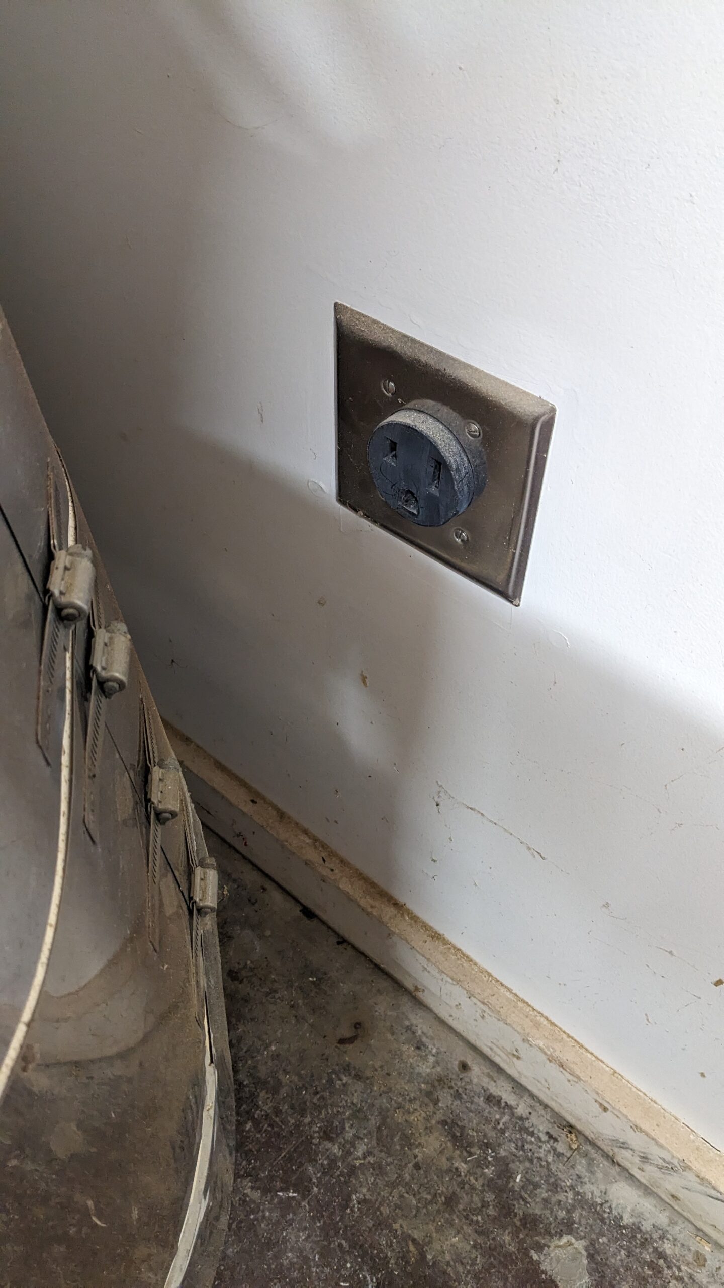
You will need a receptacle in your wall somewhere that matches the plug that you’re going to use. If you don’t know how to do this, call a licensed electrician in your area.
You will need a breaker of the correct amperage, wire in the wall of the correct gauge, and a connection to your receptacle that’s to code. If your run of wire is long, you will need a larger gauge wire to account for voltage drop. If you’re using aluminum wire, you will need a breaker and receptacle rated for aluminum (and dielectric grease). If wires go through an attic, you will need to take the ambient temperatures into account for wire selection.
All that to say… There are multiple ways this can create a serious fire hazard. If in any doubt at all, hire a professional.
The last portion of the preparation step is to ensure that your kiln is unplugged from the wall. I did this work years ago, but presumably you have a 3-phase plug and a receptacle that doesn’t match, so this shouldn’t be an issue for you.
Step 2: Get inside the controller
You will have to remove your kiln controller to get into the wiring. This just requires a 6-in-1 screwdriver that you can get for less than $5 from any hardware store.
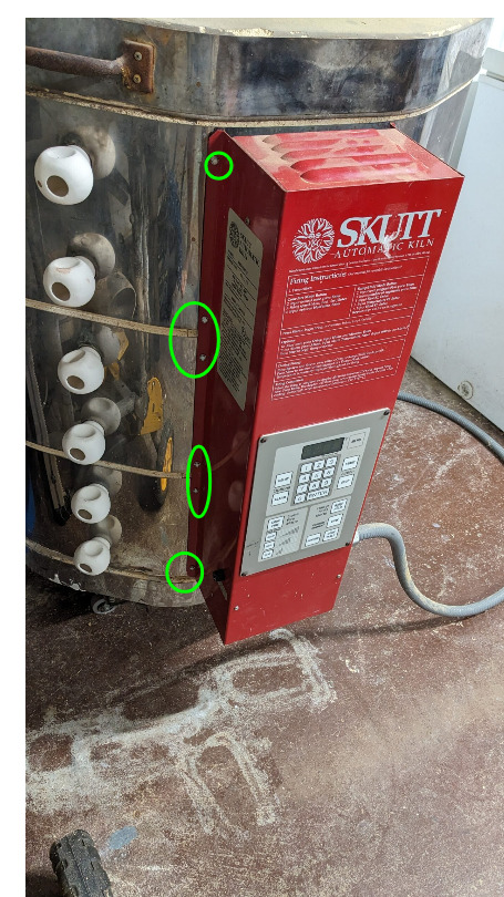
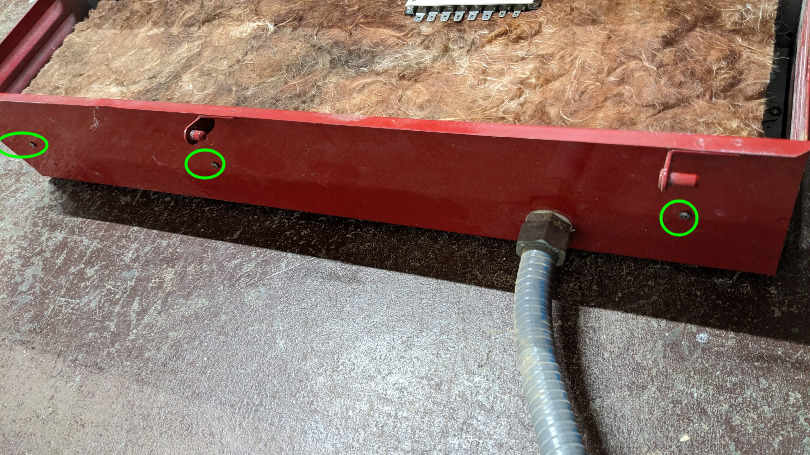
Start by removing the 6x screws that hold the controller flat to the kiln body.
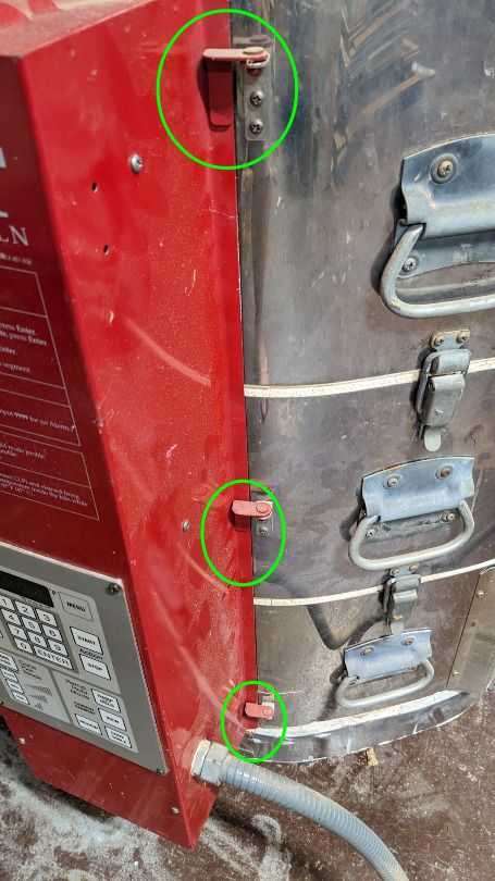
Then pivot the controller outwards on the 3x hinges.
 Don’t lift up yet, there are wires to disconnect first.
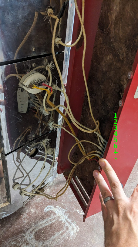
Then unplug the 8x spade connectors from the quick disconnect panel on the back of the controller. The coils should be labeled 1-6, to help put it back together quickly. But if not, grab some tape and a sharpie before pulling them off. The thermocouple wires aren’t labeled, but the ceramic mounting block has +/- symbols cast into it if you forget how it came apart.
Once freed, pull upwards on the controller and lift the pins out of the hinges.
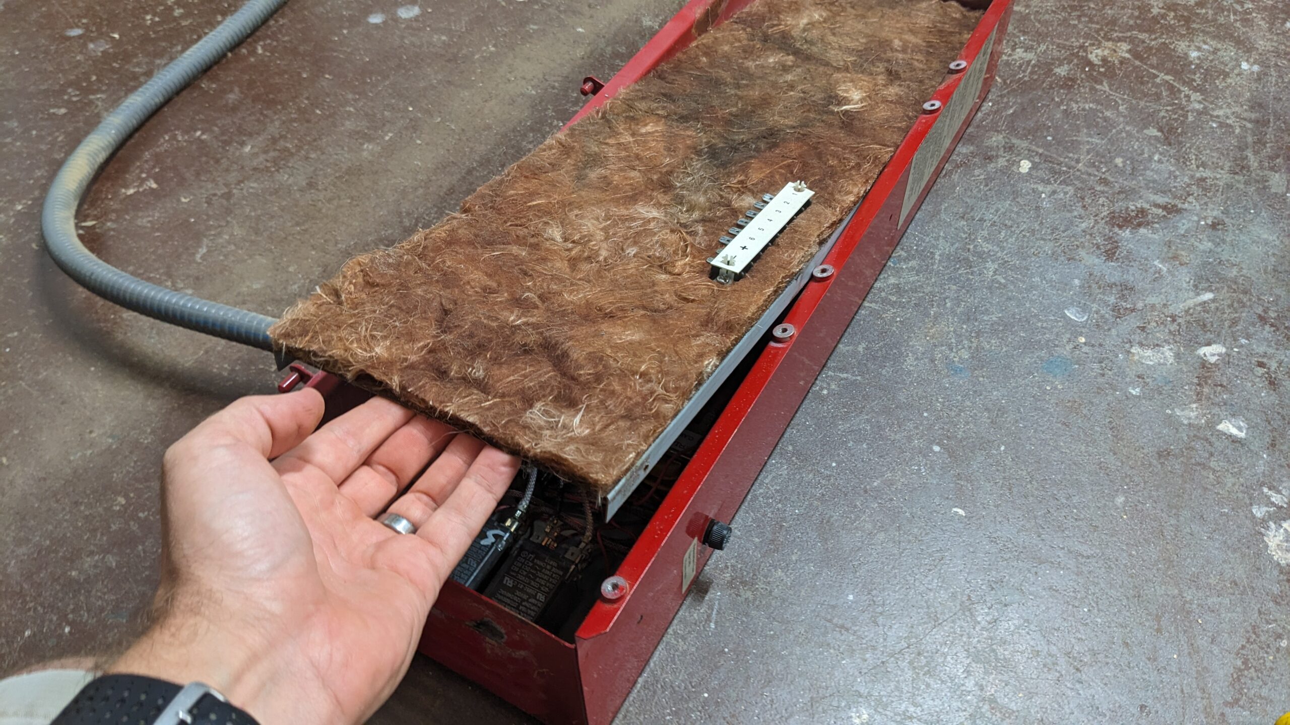
Next you will need to remove 3x screws on each side of the controller. Those hold in the aluminum plate and fiberglass insulation in place.
 Also in the same location on the opposite side.
Once removed, pull upwards. Mine was kind of tight, but it’s only friction holding it in. There are wires on the back side, so don’t pull it outward violently. You should have enough slack to set it to the side without removing more spade connectors.
Step 3: Rewire the terminal block
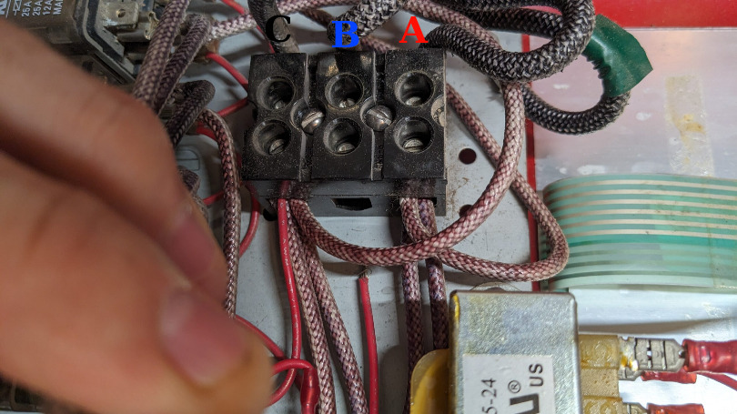
This is pretty straightforward. There is a terminal block at the heart of the kiln controller segmented into three blocks. Normally these would be phases A, B, and C (also called Line 1/2/3) going in on the left side, as pictured. Ground connects to the chassis. The relays are fed by the 3 phases.
3-phase in the U.S. should be colored red/black/blue. Ground should always be green. And a normal 240V (split phase) system in the home should have white as neutral, and red/black for the L1 and L2. So I will stick with that color code in the images below.
 I did this with a touchpad late at night. I will borrow my wife’s surface and try this again with a stylus. Just showing that L1 and L2 go into each of the 3 relays.
Each relay controls two coils, or one section/ring of the kiln. The elements are connected in parallel, so only two wires are used to power both elements/coils of a section.
The right side of the terminal block is where the outputs go, which feed into the relays. For 3 phase power, each relay is connected to a different pair of phases to equally spread the load amongst your power delivery system. In single phase every single relay gets line voltage wired the same; one side to the right, and the other to the left of the relay.
| 3-phase | Single Phase | |
|---|---|---|
| Relay 1 | A/B | A/C |
| Relay 2 | B/C | A/C |
| Relay 3 | A/C | A/C |
And here are the diagrams directly from the KilnMaster manual, which you can get from Skutt easily, with the “resources” link on their website. This should be much easier to read, even without being color coded.
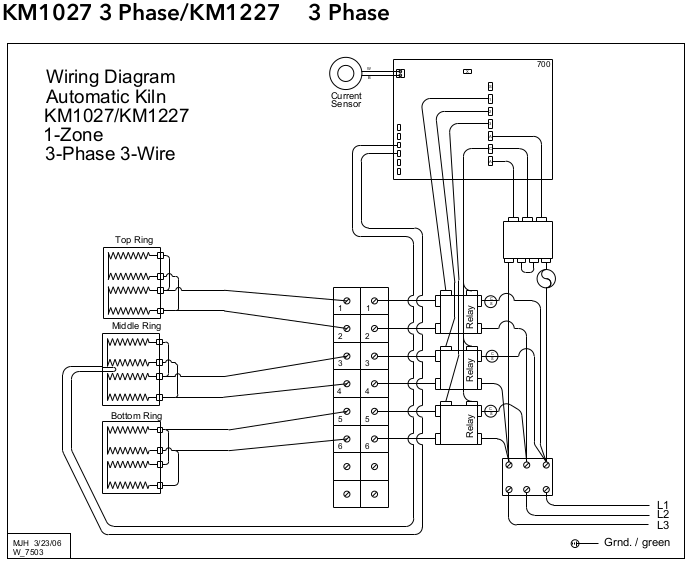 The original config.
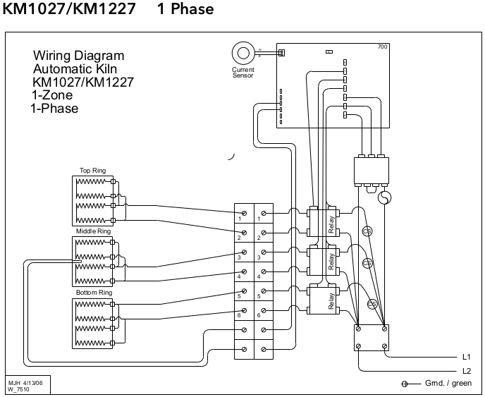 The new config.
The terminal block is able to acommodate all three output wires together into one slot. So grab the input of each relay, either right or left, and stick them into the terminal block top (phase A). Then grab the opposite from each relay, the only 3x that should be remaining, and put them into the bottom block (what used to be phase C).
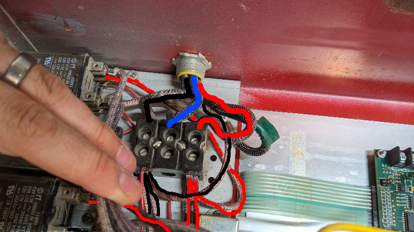 Wires coming in from the plug, into the terminal block. (this is the new configuration, not what you’d be seeing initially)
Notes:
-
Phase B, the middle, is unused in the new configuration. We’re leaving this firmly connected to the terminal block, so that it isn’t free floating inside of the kiln controller box. You’ll see why later. And we may as well leave the two hot lines with 240 volts AC with as much separation as possible, as best practice.
-
You shouldn’t have to pull anything off of the relays. But if you do, they’re setup in this manner:
| Connector | Use |
|---|---|
| Top (as mounted in the controller) | Unused |
| Middle top | Outputs to the connector block (spade terminals on either side of the insulation) |
| Middle bottom | Input line voltages from the terminal block |
| Bottom | Red control wires, from the control board and transformer |
Step 4: Replace the plug
This is fairly simple compared to what we just did. I bought my NEMA 6-50P (P for plug, R for receptacle) at Lowe’s for relatively cheap ($16 today). It’s UL listed, and doesn’t see much hard use, so I don’t need to spend $50 on a beefy one that withstand a car being driven over it.
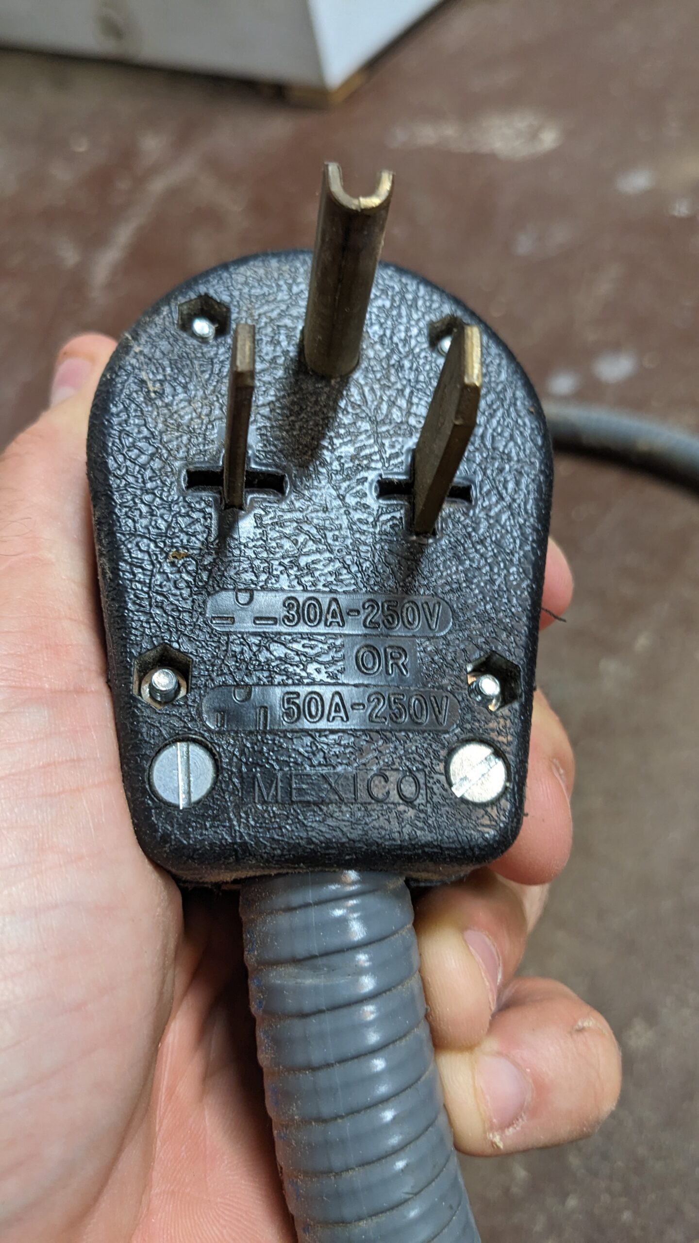 This one has prongs that can be vertical or horizontal, to support both 50A and 30A configurations.
Yes, $75 plugs are a thing. The NEMA 15-50P that came on the kiln from the school district was actually very expensive brand new. I didn’t need it, and ended up selling it used on ebay for like $30 to someone that needed it. Beer isn’t going to buy itself. But I digress.
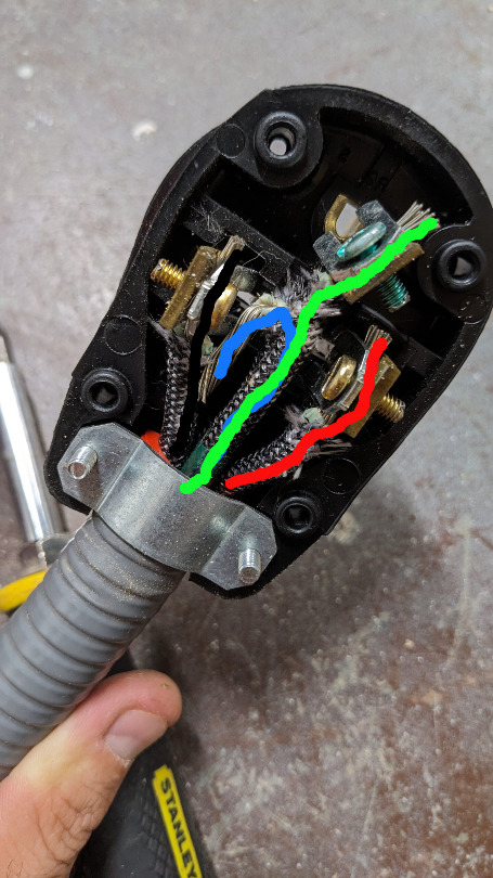
On my kiln the ground is marked with some high temp green tape on each end. I suspect most from the OEM are like this, but your mileage may vary. You still have one wire that is unused. So you will need a multimeter or test light to establish continuity between what we just finished up in the controller, and this plug.
I took the unused wire formerly known as phase B, and bent the strands over. At the time I didn’t have any heat shrink tube. The bare conductors could very easily wiggle around inside the plug and make contact with one of the two hot lines. This is why the other end of phase B is still firmly attached to the terminal block all by its lonesome. If that happened, and the end inside the controller were free floating as well… it would likely short against ground somewhere inside the controller box. At best this will pop a breaker. At worst it could arc, get hot, and burn your house down.
You could also completely remove the unused conductor from your cord. This is probably the safest option. But if I ever want to convert this back to 3-phase, I don’t want to re-pull everything through the flexible conduit.
Anyways, connect the ground/neutral to the ground prong. Connect the other two to the left and right prongs. It’s alternating current and it’s grounded, so it doesn’t really matter which of the two hot wires goes to which prong.
This is tinned copper. If you have aluminum for some reason you will need the appropriate plug, and some dielectric grease (again, we don’t like house fires).
Ensure it’s clamped tightly to the flex conduit (if your setup has flex conduit) and close up the connector with the screws.
Stop here! Do not plug in yet!
There is a part 2 inbound, and hopefully I will be able to get to posting it soon. If you plug this in right now, you could start a fire.
The 3-phase setup uses heating elements that are of lower resistance than that of a 240V unit. This is because 3-phase is only 208 volts. So to get the same power output that supports getting up to cone 10 temperatures… we need more amperage at that lower voltage.
So if you plug this in right now, you can draw more current than the factory heating elements are intended to draw. See this chart for the actual numbers. You can buy the correct coils from Skutt or another supplier (for the 240V single phase unit) and replace them all.
But in part 2 I’m going to show you how to make your own coils for cheap with a drill, some steel round bar, some washers, and some math in an excel spreadsheet.
If you’re willing to get your hands dirty to save a few hundred bucks, check back for part 2 soon!