The problem
The middle child got a Creality CR-10 Smart for free a while ago. From one of the other kids on the robotics team I think. It was working intermittently, and they weren’t sure why. I guess high school kids aren’t particularly well equipped to deal with things like this. In their defense, this printer is a bit of an oddity. And if they’re wealthy enough to throw away what was a $500-600 printer, I’m not going to turn my nose up at it.
It sat in his room for about a year unused. We poked and prodded at it, but never could get it to work right. Ultimately mom issued a decree: “Thou shalt get this broken thing working, or thou shalt have the broken crap donated to the thrift store!”
After the decree was issued, the christmas list miraculously included a new screen for the printer. Who knew it was that easy?
The actual problem was that it would go unresponsive randomly during printing. Sometimes 30 seconds after starting, sometimes 5 minutes. The screen would just lock up, and nothing would bring it back.
I had updated the screen firmware, updated the mainboard firmware, and updated the smart module firmware. All of these were from the same released configuration on Creality’s own website.
I also unhooked the smart module, and sent commands directly from a RPi-3B running OctoPrint, as well as PuTTY on my laptop. This was done with and without the screen connected, and yielded the same results. No screen locking up obviously, since it wasn’t attached. But the mainboard was throwing errors over serial.
How does this thing work?
It’s a lot of pieces that seem to be smashed together, without great care being taken. If I had to wager a guess, I’d say that this thing had a tight deadline because there was a sector of the market with a void, production issues with other items, etc. But who knows.
1 - Creality Box
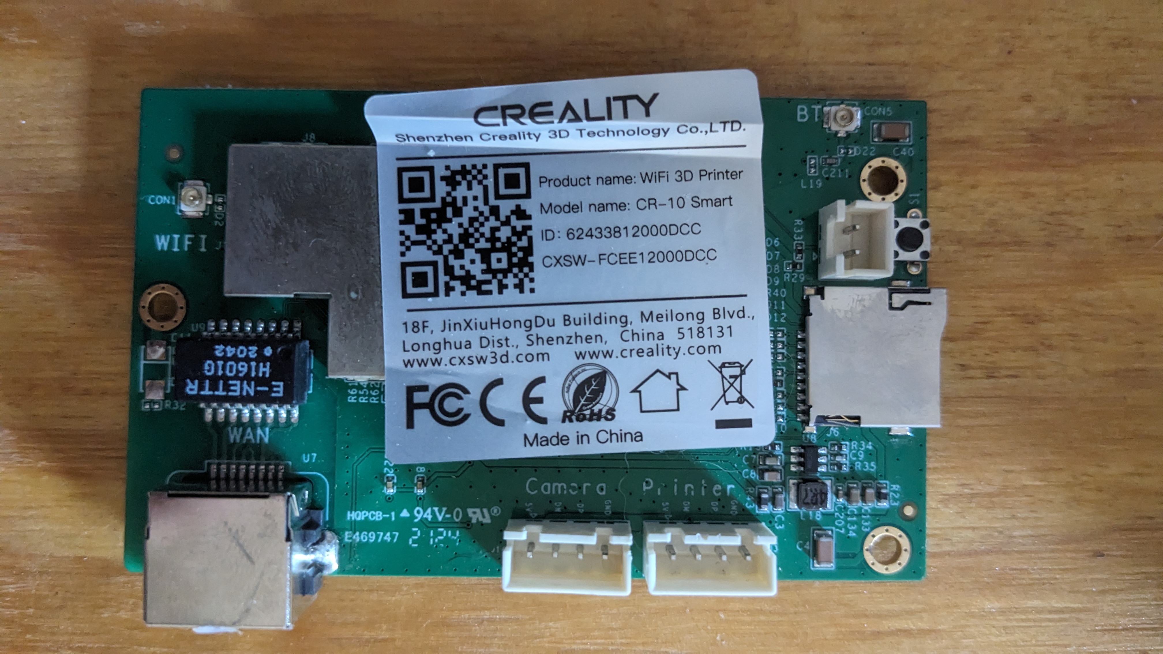 The board in the CR-10 Smart.
 Is just a shucked Creality Box, with some different connectors soldered on.
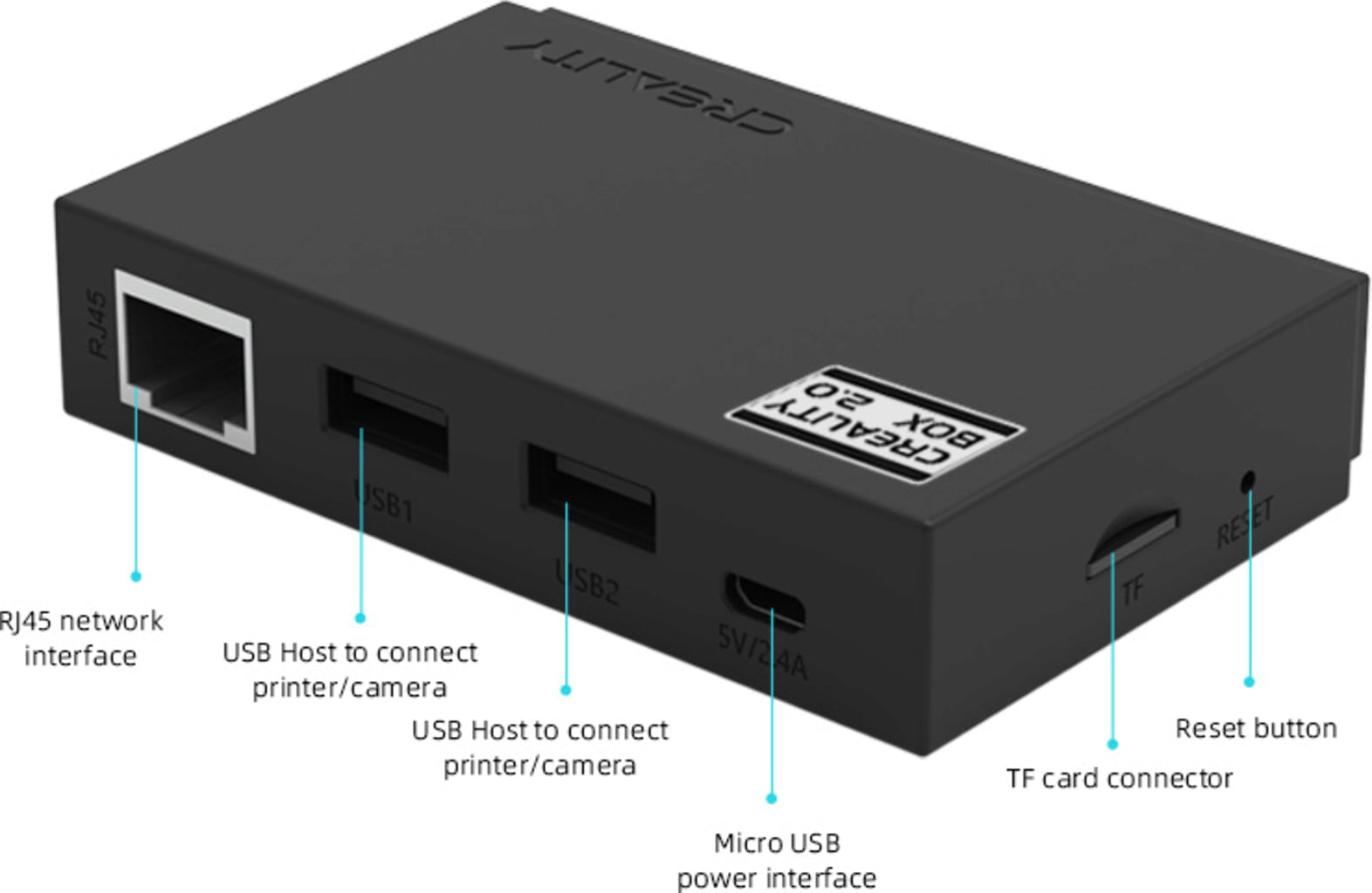
What I’ve already called a “smart module”. This is just what’s in the Creality Box, sans the case. A Mediatek MT7688AN SoC on a small board for I/O (teardown here). It has a wifi and bluetooth antenna, wired ethernet. A USB header output connects to the mainboard to control it. An external USB port is wired to a passthrough on the side of the unit. It can be used for webcam monitoring, but only works on their own webcam, not a leftover generic one like we all use for OctoPrint. It has an SD card, which looks to be used only for upgrading firmware.
You scan a QR code on the printer in the Creality app to onboard the printer initially. I think it’s just the MAC address of the bluetooth antenna. It’s also not the only QR code on the printer, and is the smaller of the two that are front and center. Which screams “amateur hour”. Once you’re connected to BT, you give it your wifi credentials, it connects there, then bluetooth is unused. Similar to a lot of other cheap smart devices that exist nowadays.
It’s not fast enough to run OctoPrint reliably. Some have gotten it to work for Klipper with KlipperWRT. Others have installed OpenWRT onto it, then installed OctoPrint manually with limited success. The instructions look like a pain in the rear.
The plan: Rip it out and put it in a cardboard box. It may be used later, or may be prodded and documented. But for now is a vestigial organ.
2 - Mainboard
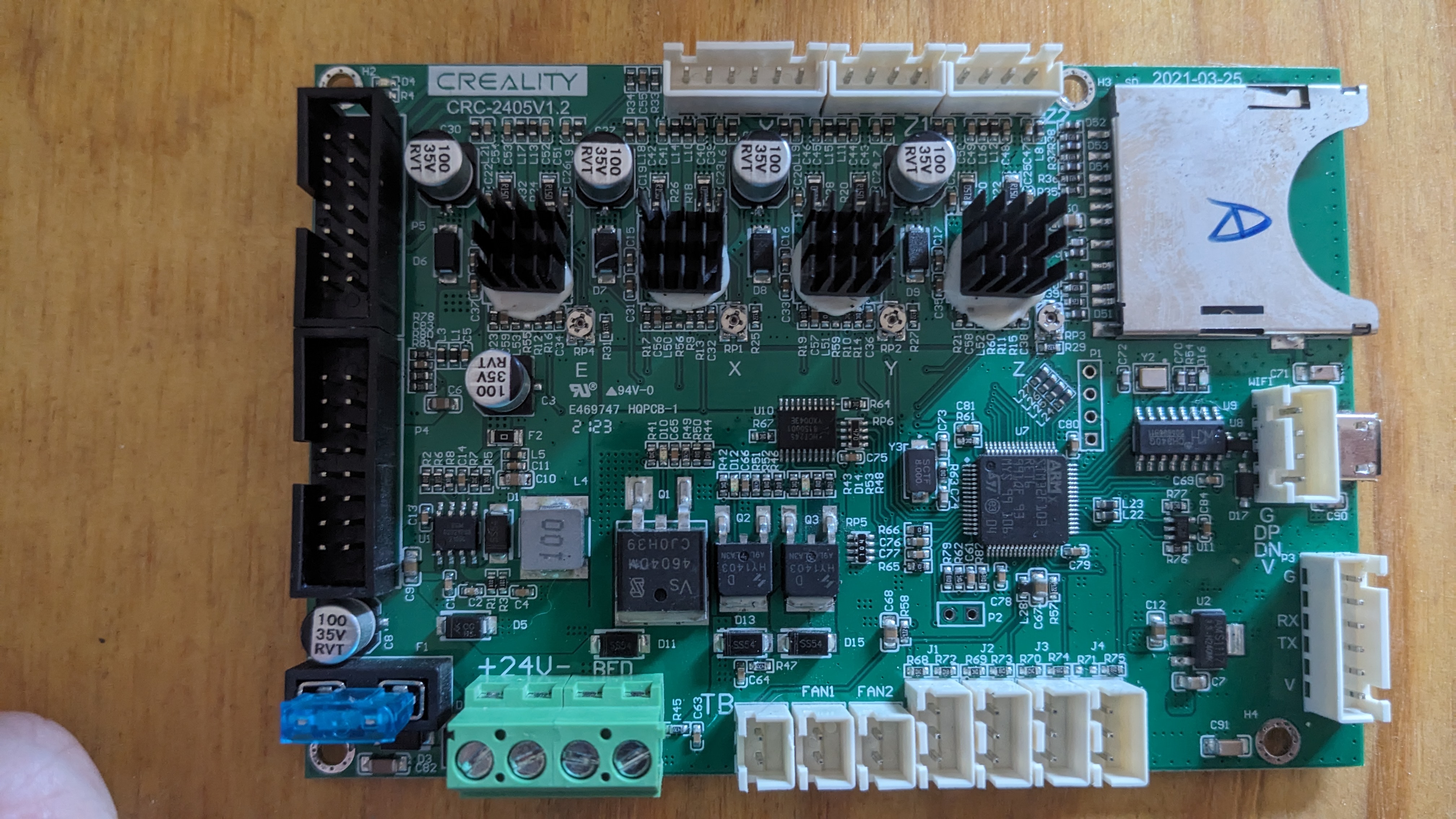
This is a CRC-2405V1.2. As far as I can tell it’s not used on any other printers besides CR-10 and CR-6. I know Creality is cheap, and likes to re-use products to save on development money. Which tells me that this thing is unreliable and was probably ditched.
It has a STM32F103 processor. There is community firmware available out there. But there is also mention of some DRM in the bootloader that allows you to install a firmware file only once. Presumably you can just rename a firmware file to something new and get around that. But there’s no way (that I’ve found) to determine what’s already been used. Or maybe the space available in non-volatile memory (NVM) for this is already full from trying to fix it too many times already. I figured I could just manually pull firmware by de-soldering some flash module, or doing a chip-on extraction. But there is no flash on the board to desolder and pull firmware from. The flash is all internal to the ARM system-on-chip (SOC).
There is one USB input from the smart module. I didn’t mess with it much, but wasn’t able to get a serial console here. There’s also a USB micro-B point towards the front of the board that’s not used (and isn’t even accessible.) I tried connecting to here, and didn’t have luck either. I’m assuming it was disabled when they build the firmware.
With some more digging, I think a board diagram could be found and made sense of. With the oscilloscope or logic analyzer we could probe some pins and maybe get a serial console. But I’m honestly not that invested, since so many people have not had luck with this thing.
The plan: Pull out for now, get a new mainboard that’s better documented.
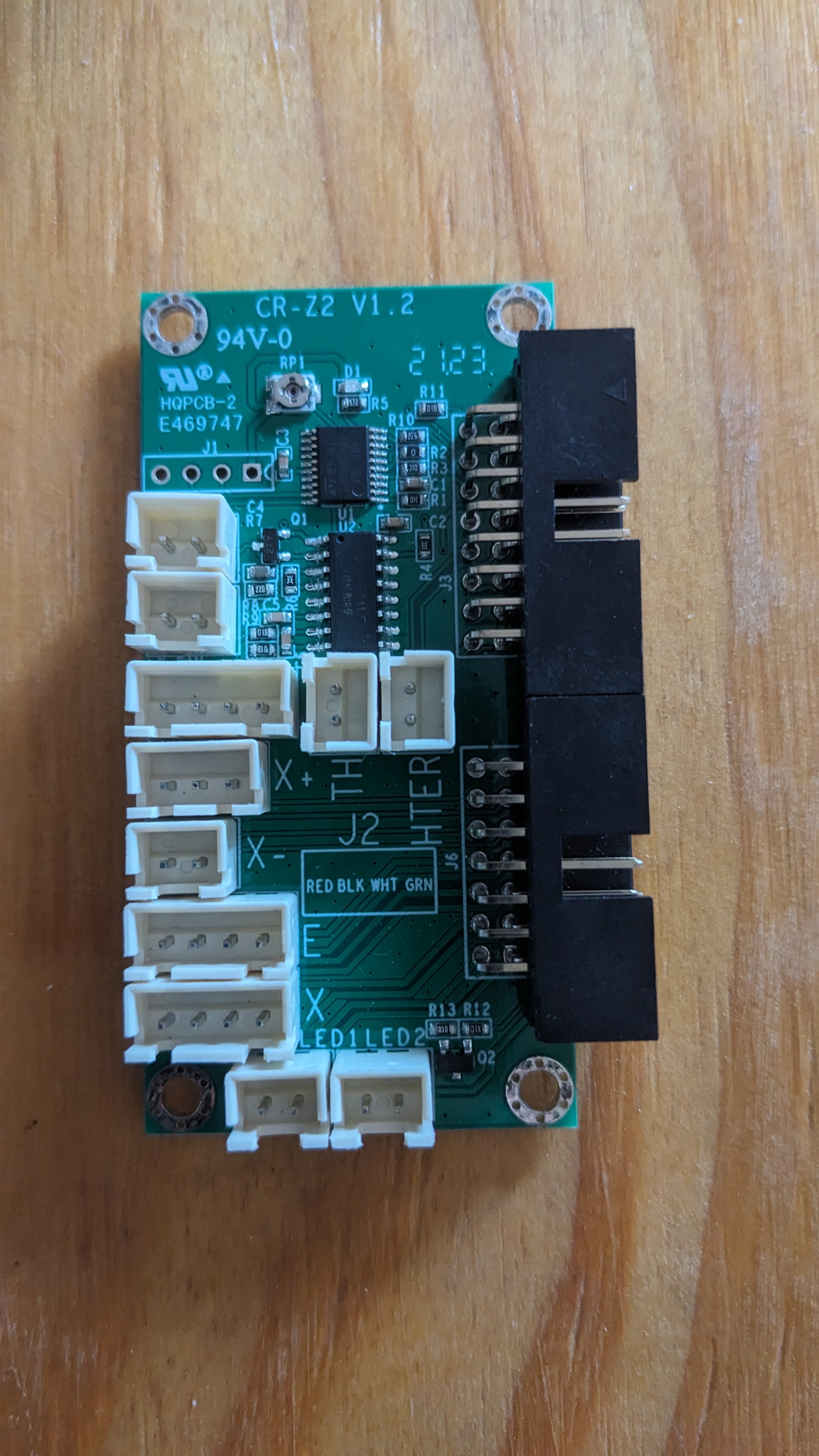
3 - Power board
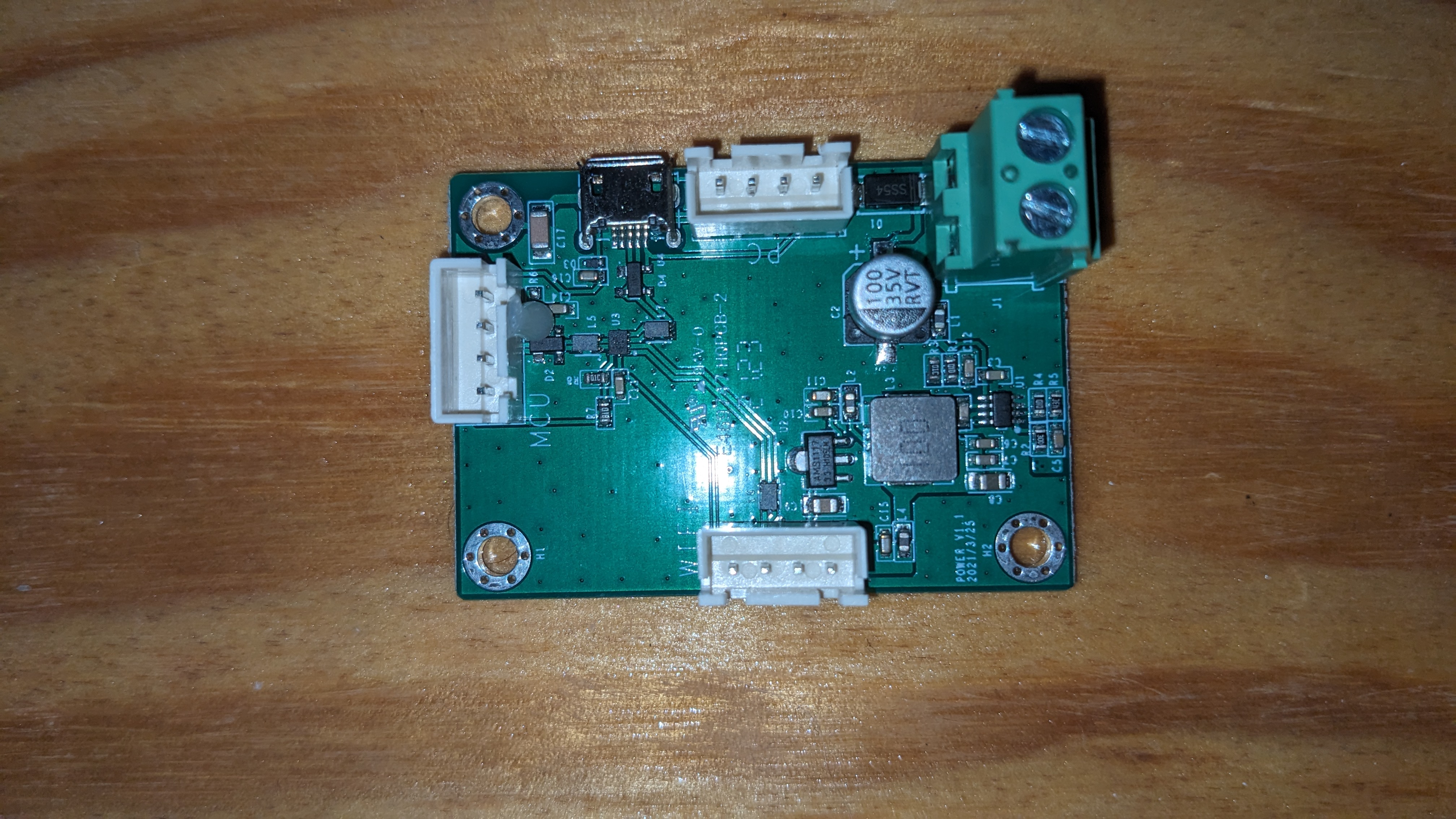 This is an intermediate board that seems to be multiplexing serial connections, and also has a 24VDC input. Not sure entirely how this works along with the OEM relay board yet. But will dig into this later.
This thing has the ability to turn itself off some amount of time after finishing a print, if there is an overheat condition, etc. That’s a pretty good feature for a printer designed by the OEM to be walked away from and monitored remotely.
There’s a rocker switch at the power inlet on the back of the machine. There’s also a momentary push button on the side which connects the PSU. So it gives the printer power initially. Their custom version of Marlin gets through the bootstrapper enough to start running, and eventually applies power to an output pin that turns on the relay in the power board. At this point you can release the button and it will stay on. The screen goes through its bootup cycle, etc.
The plan: It is a relatively generic piece of kit, so it’s staying in for now. But it required 24V input to drive the relay, so it won’t work well with a new board that outputs 5V or 3.3V logic on the spare pins we have. I may modify it with a transistor and 24V from the PSU. Or I may replace it entirely with some spare relays I used for my own printer (for the heated enclosure mod that I did).
4 - Hot End
I like the cable management on this thing. There’s a 2x7 ribbon cable, and another 2x8 for a total of 30x pins. There is a breakout board up top on the gantry that the steppers, X axis end stop, thermistor, etc. plug into.
 The breakout board for the ribbon cables that lives on the gantry.
The problem… is that it’s not a passive component. It has its own ARM M0 (STM32F030) processor up there. “What exactly is it doing up there?” You may ask yourself, as I did… Well, the bed leveling on this thing is a little funky, to say the least.
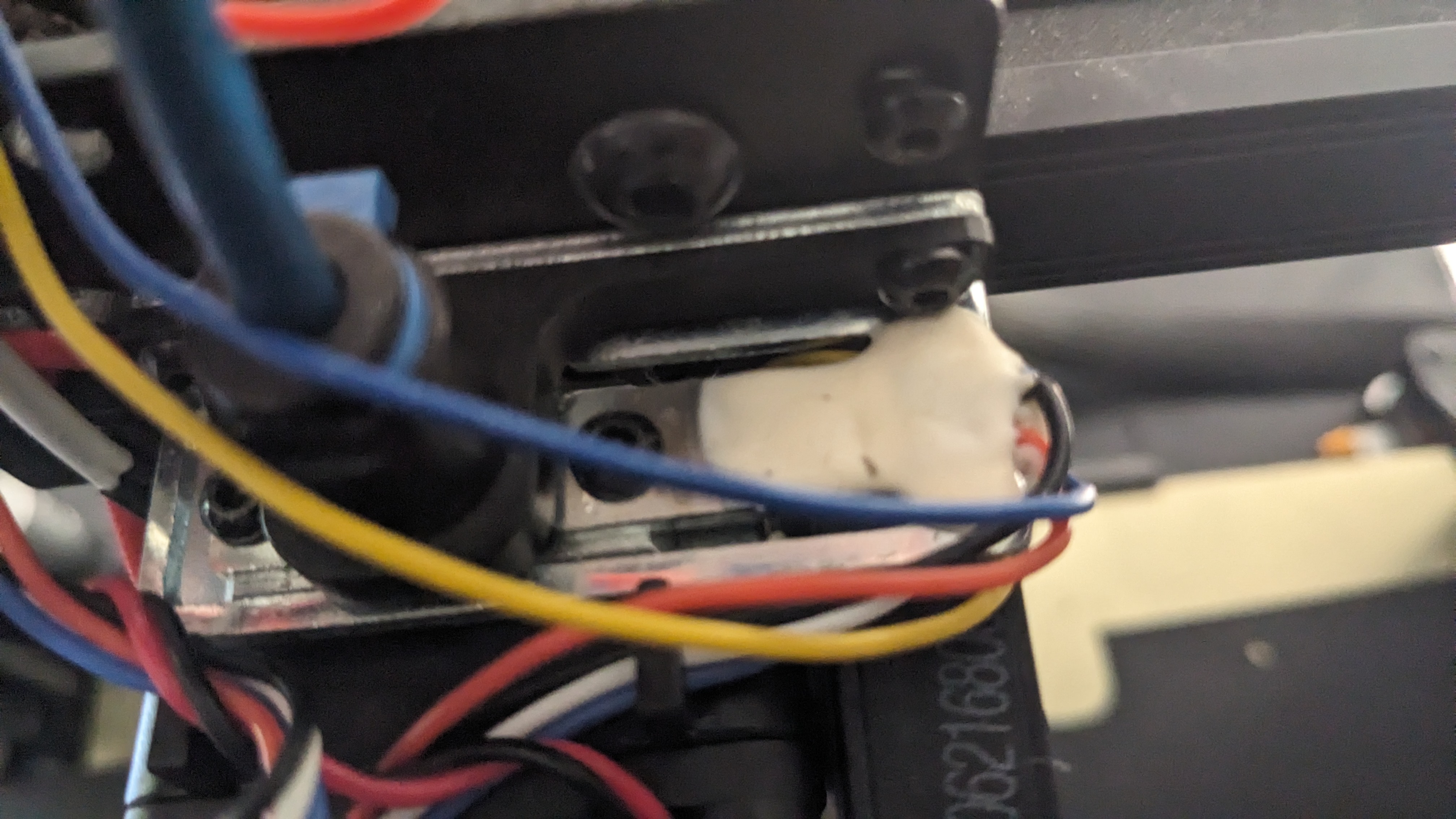 Strain Gauge(s) potted on the right, and hot end sits below on the left (see the screws).
The hot end heat brake is mounted to a small aluminum bar up top. That aluminum bar stock has (from what I can tell, it’s encased in white epoxy) a bi-axial strain gauge. The breakout board has a HX711 24-bit ADC chip on it that’s managing the strain gauge outputs. This isn’t a bad thing, even with resistors of very tight tolerance in our wheatstone bridge, we’re generating somewhere in the range of single-digit millivolts on these strin gauges, at the few pounds of force we’re generating here. So that’s going to be necessary.
Then this chip is giving results to the ARM chip, which in turn has its own firmware and is sending results back down to the mainboard in some format that is not well documented.
The plan: Just unplug it for now. I’m not spending money on a new hot end. The hot end itself isn’t broken, just one of the functions that it has. I may thrown on a BLTouch, or try and get sensorless homing to work, although that will be slightly difficult with two Z steppers, and a worm drive that’s giving a mechanical advantage.
5 - The screen
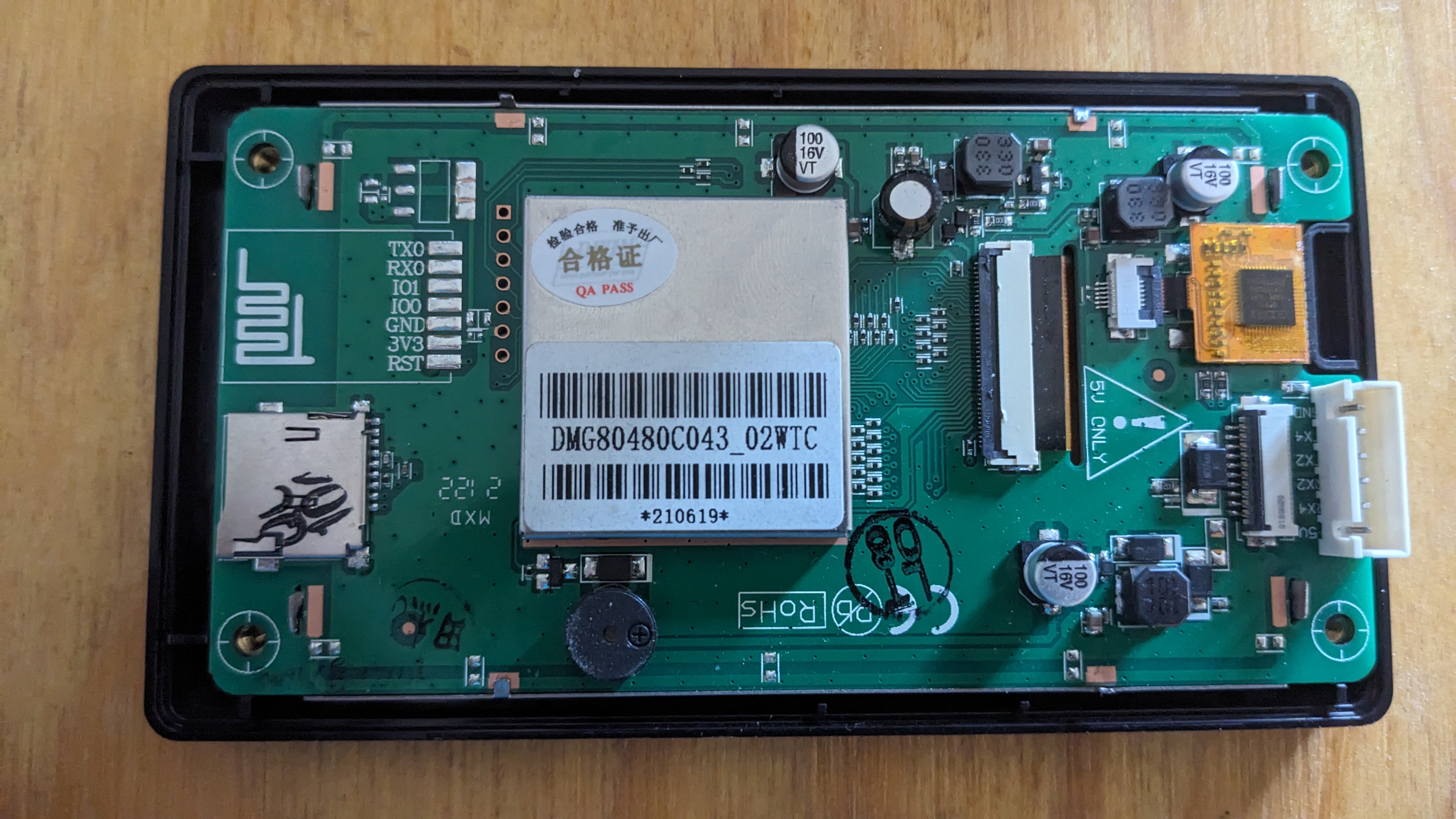
This isn’t really made by Creality, just the housing. It’s made by a Chinese company called DWIN. They make some (in my opinion, fairly low quality) human machine interface (HMI) systems. They have 3 layers in this housing.
- The controller board. Running DWIN’s own bootloader and firmware. It has what they call a “firmware” file that you upload for your application. But it’s really just a number of bitmap images for background screens and buttons. Behavior for sliders and whatnot on the touchscreen. And some pre-packaged commands to be sent over the serial console when the touchscreen is used.
You can read more about it here. The software is free to download and mess around with, but it’s clunky. I tried creating a very simple interface of my own to troubleshoot the screen. documentation is not great, menu items are sometimes still in Chinese only. Translations to english are hard to understand, etc.
They have an entire schema of their own. Header, message size, message type, memory address to modify, and payload. It’s… a whole thing. One that I don’t feel like messing with. I deal with enough oddball interfaces and data structures at work (MIL-STD-1553, MIL-STD-6016, tons of proprietary hardware and software encryption layers, etc.). I’m not all that keen on learning yet another proprietary standard. Especially one that is neither making me money, or ubiquitous in my hobby projects.
-
The LCD screen itself. Not much to say. Just connected to the controller board with a ribbon cable. They have different sizes and resolutions to choose from to create your own HMI stack, if you’re in the market.
-
The digitizer. Connected to the controller board with its own 6-pin ribbon. Uses an I2C interface. I ended up buying a breakout board for this pitch of ribbon cable, and using the I2C interface on a spare RPi to test it out. From what I can tell, the interface is dead. So I think ultimately the screen is dead because someone dropped it, poked it too hard, or the bit of active circuitry (directly soldered on the ribbon cable) overheated or something. But there are no signs of damage that I can see.
The plan: Get rid of this, and use a Big Tree Tech screen with better support. You can’t buy the individual slices of these things from DWIN. Sometimes you can find whole units, but they’re fairly expensive nowadays. Like ~$80 or more, with no guarantees that it works. I even tried to e-mail DWIN directly to get a digitizer, and they never even responded. So good luck if you’re a consumer who just wants 1 unit. I’m not holding my breath.
The plan
If you read all of that… it’s clear that there are a lot of subsystems in this thing. They’ve all been haphazardly smashed together. And each of the systems individually have problems that make them less than ideal for an open-source solution that is reliable and easy to fix (or upgrade) ourselves in the future.
I’m loosely following the build that I found from Embrace Making. So I’m going with a Big Tree Tech SKR Mini E3 V3, and their TFT 35 screen to go along with it.
The mainboard will connect with short jumpers to a breakout board in the bottom portion of the printer. This will be very similar to what’s up top on the gantry. Then the OEM ribbon cables will carry the signals up to the gantry. Then they’ll get to another breakout board to, well… break them back out. But this one will be purely a passive device.
The port for the NeoPixel LED(s) will be unpopulated for now. But would be a nice feature to have in the future. I really like the idea of having colors and blink codes right in front to give an indication of what’s going on while heating, etc.
The BLTouch, as already mentioned, will also remain unpopulated for now. But may be used in the future depending on my luck with the rest of it.
Power will go through the main rocker switch only to start with. I’ll either use the BTT relay, one of my own spares, or modify the system to get the OEM relay board to work with a lower logic voltage.
I started ordering the parts (because it was almost christmas, and the boy needed some gifts). But by the time I had already made the purchase, I noticed that this guy does not in fact have board schematics on his github. But he does sell them for $45!
And can we talk for a minute about how firmware is on github, but not any config files to make it actually work? The .stl files for new printer components (to mount the new mainboard on existing posts, new screen housing, etc.) are on printables. There’s a youtube video that covers some of it. There’s a blog post that covers some of it. And a big portion just isn’t really covered at all to the point that you, dear reader, could actually modify it for yourself. EmbraceMaking, if you’re reading this… Get your life together, bro. Put everything together in one place that’s easy to grab. Rant over.
I know how much it costs to have PCBWay or JLCPCB make something this size with nothing but passive components. It’s not even close to that expensive. And I also don’t like not having control of the schematic to modify it if I want to. So I’m making my own in KiCAD. I plan on releasing the files so you can make your own, and soldering up a few and selling them pre-assembled for close to the cost of the components. The 2x7 and 2x8 headers are like $1.50/ea for some nice Amphenol ones. It should be $10-20 total for both breakout boards all said and done.
Upcoming
Part 2
My next post will be about the breakout boards and some design considerations in KiCAD. It should be fairly short, since I’m not an electrical engineer, and this is just a passive board with low currents and slow baud rates. But I had fun making it, so I’ll share what I have.
Part 3
This will cover Marlin Firmware. Embrace Making has a firmware.bin file available, but doesn’t talk about what he’s got in there. He used a different hot end, a BLTouch, and a NeoPixel. So if you want to follow what he’s got exactly, you’re golden. But if you want to omit any of that, or modify individual behaviors, you’re SOL. Like sensorless homing. the mainboard has 2209 stepper drivers, so I’m not sure why anyone wouldn’t try and use that, at least for X and Y.
Anyways, I will release the actual firmware along with my config files so you can build it yourself. I used Marlin v2.0.9.7, and there were some bugs that kept it from compiling. E.g. Marlin uses PlatformIO, and some PIO changes in newer versions broke functionality during build. So I’ll walk through the few changes that were required to get it to build.
Part 4
I’ll have everything put together at this point, and may have some modifications to the firmware. At the time of writing part 1, I don’t have my breakout boards in the mail yet. They actually just shipped a few hours ago. So in theory it all works, but I wouldn’t be surprised if there are some minor changes required.
Part 5
Is hopefully not needed. But I have a feeling sensorless homing on the Z axis will be finicky, and I will end up wanting a BLTouch to make things more reliable and predictable. This is ultimately for a teenage boy, and I don’t expect him to modify and compile his own firmware to chase down electrical demons. He’s not quite there yet (but I still have hope for him!)