Overview
As I said in my previous post, I really kind of like the way the CR-10 Smart uses ribbon cables between the base and the gantry. My first printer was (and still is) a Ender 5 Pro, which just has individual cables strung all the way up to the top. It’s ok, but becomes a rat’s nest whenever you have to do any work on it, like swapping out a thermistor, heater cartridge, hot end fan, etc.
The goal is to keep those ribbon cables, and have a breakout board on each end. I could have used the BTT SKR CR-6 mainboard which is pin compatible with the original mainboard. The SKR CR6 is designed to use the strain gauge system, which I want to divest of. I don’t want to deal with firmware peculiarities, or use someone else’s firmware that I can’t modify easily. The SKR Mini E3 V3 has a 5-pin header just for the BLTouch bed leveling system. So we’re using that instead.
So we’ll go from the mainboard to the bottom breakout board. Just using pigtails for each function, that are pinned in the same order on both ends. Then the bottom breakout plugs into the ribbon cable.
Because of the way ribbon cables are, if you orient the connector in the same way on top and bottom (looking at it from the top down into the board, notch on the same side), each pin lines up exactly with its counterpart on the other end.
Then from the top breakout board, we go into each of the individual components again. Extruder and X steppers, hot end fan, extruder fan, thermistor, etc.
Design
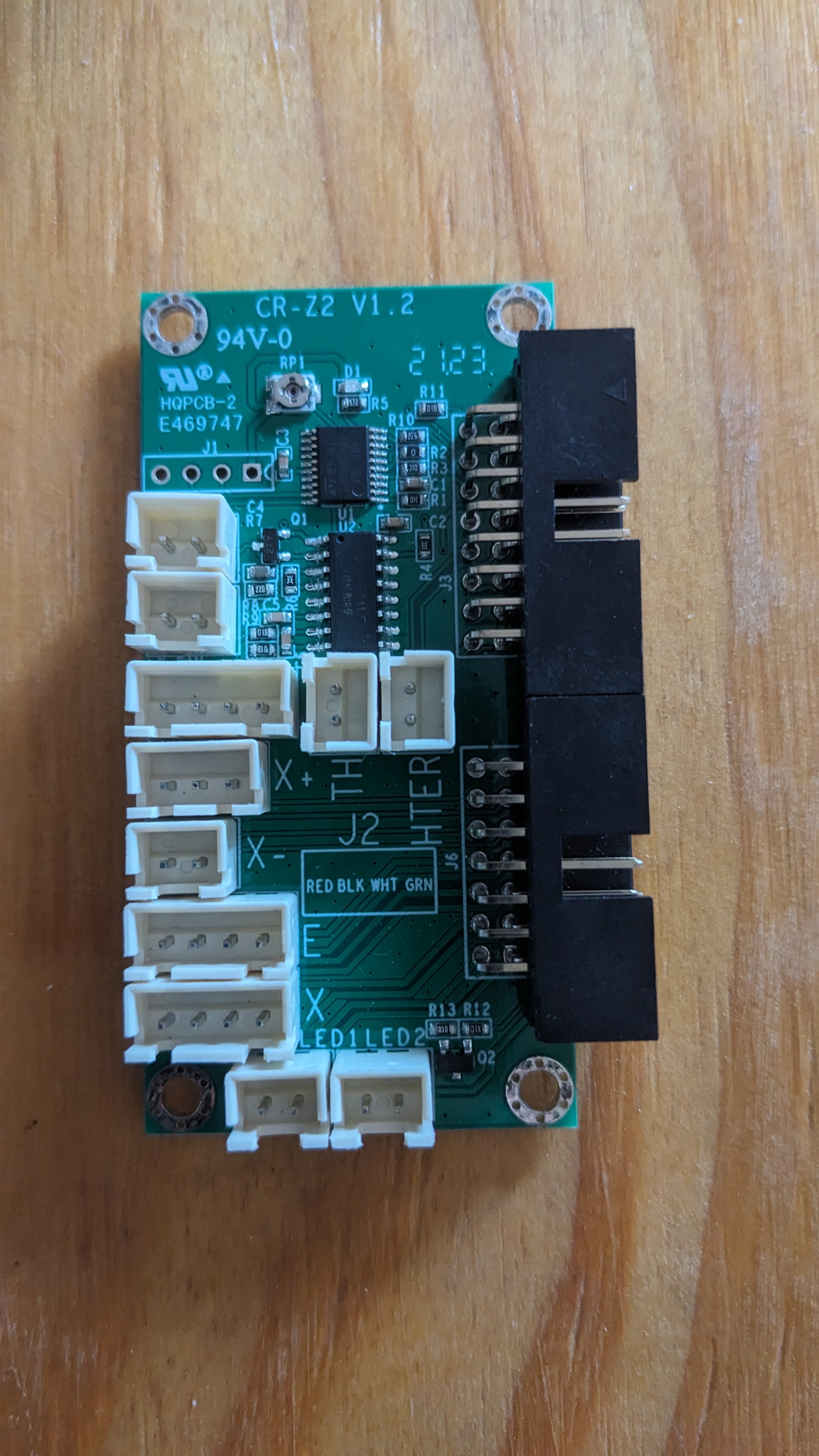
Recall from my original post that the original breakout board has a few things we don’t want.
- It uses the strain gauges on the hot end mount. These will stay in place for now and just not be plugged in. I might cut these wires off, or scrape the gauges off of the aluminum bar entirely if I care enough.
- It has 2x LEDs on the front cover (near the x-stop). These are intended to light up a part for the webcam. But they’re not very bright, and we don’t need them.
Design Considerations
-
The x-stop should be unused since I’m shooting for sensorless homing. But the header for it will need to be included as a fallback.
-
The ribbon cables originally use 3x wires for power and another 3x for switched ground, to drive the hot end heater cartridge. I don’t want to take up 6x pins just for that, and am going to run some stranded wire separately up to the top straight off of the mainboard output. It’ll come into the top breakout with screw terminals, and go straight into a 1x2 pinheader to use the original heater.
-
Trying to use the same exact breakout board on top and bottom. Because of the properties of ribbon cables that I wrote about above, this is works out well since the minimum order at JLCPCB is 5x. So I won’t end up with 5x of each part, and 4x of each as spares. I’ll have 3x spares of just the one part.
For now, the only difference will be that the bottom one will have vertical ribbon cable headers, and the top will have right-angle to match what’s already there. I may redesign this in the future to manage cabling better, and use existing mounting posts in the printer base. Or not.
- I’m not combining 3.3V, 5V, and ground supplies for different components. I’m not sure if the mainboard runs those all off of the same voltage rails. If not, I don’t want to bridge any of those and cause shorts between voltage converters. So each component will be a straight pin-pin from top to bottom.
I could reduce the amount of pins I’m using, I know. But this is safer, and might prevent someone from frying a mainboard if they don’t know what they’re doing. It also means that the 1x2 header for the x-stop could be used for anything you want that’s also 2 pins. No worries about how it’s interacting with other components, because it’s isolated.
-
Planning for 2.5A of current on the steppers (which is a little overkill). So I’m going with 2oz copper on the PCB, which means about 21mil trace width.
-
I’m using the existing mounting holes and plastic shroud on the top breakout board. So the screw terminals for the extruder heat will have to sit behind the ribbon cables, and the wires will be routed over top of the ribbons back to where they need to go.
Let’s get to it
I’m relatively new to KiCAD and PCB design in general. It’s not really in my wheelhouse with what I do professionally (besides making sure other people’s designs are producible, managing heat properly, holding up to vibrations, etc.) So bear with me if I’m doing anything stupid.
I loaded up the DigiKey parts library. But for some reason the naming conventions on the 2x7 and 2x8 footprints doesn’t match at all. I ended up modifying the footprints manually to help keep track of the pin orentation left-right in my head. I just dragged them around manually and offset the ones on the right. There’s probably an easier way to do this, but I’m a noob at this.
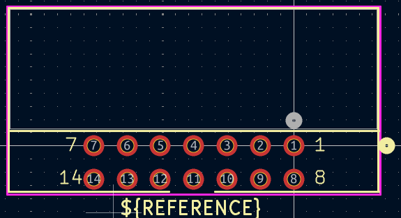 2x7 footprint
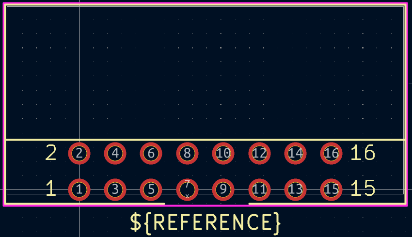 2x8 footprint
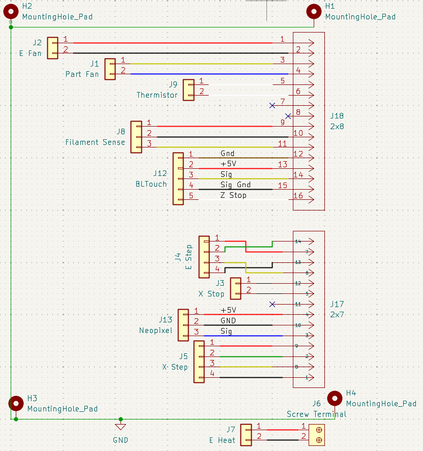
Here’s the schematic that I made up. At this point I’m mostly just trying to keep things together in a way that’s tidy. I’m also trying to keep sensitive things like the thermistor traces away from switching voltages, like the steppers. I don’t want the (relatively) high current of steppers generating some crosstalk in the thermistor and giving erroneous readings.
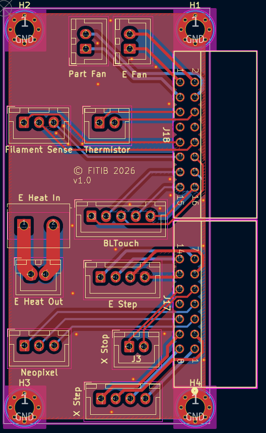
I put the extruders on each end of one of the ribbons, to make routing easier later on. 21mil trace width wasn’t working well to get between the pins of the larger headers. So I had to resort to 2x on top, 2x on bottom and using the limited space between the header and the board edge to just go around.
Red is the top layer, blue is bottom. You can see the extruder traces on each end, half on each side of the board. I wanted to keep the A and B windings together, and keep all four of them generally parallel. So the source and return amperage should help cancel fields out (I’m far from an EM fields expert), and like I already said, minimize crosstalk on other nets.
Although it’s not really important anymore, I made sure to add notes on the board with the pins on each corner (1, 2, 15, 16) for each of the ribbons. There’s plenty of space, and if it helps someone when running things from top-bottom of the whole printer, then it’s been useful.
And here’s what it will look like in the end. I don’t have the actual boards in hand yet as I’m writing this. They’re a few days away in transit still.
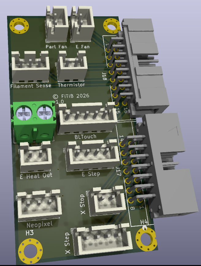
Don’t worry about the mismatch between the two large headers. I had to search a surprising amount to find .step files, and ended up getting the 2x7 and 2x8 from completely different manufacturers.
The files
And here are the KiCAD files in a 7zip file.
The “ribbon_adapter” folder contains all of the KiCAD project files. There is a sub-folder in there called “CAM” which has all of the gerber outputs intended for your PCB manufacturer of choice. Those have ultimately been combined into their own “RibbonAdapter_v1.zip” file, which is what most PCB manufacturers want for processing your order.
In the root is a “documentation” folder which just has .pdf files of board pinouts, etc. if anyone needs them.
Another “KiCAD_supplemental” folder has the 3D .step files and footprint files that I used, which were not in the standard KiCAD parts library initially.
Conclusion
I have included a license file, which allows you to use these free of charge, as long as you don’t sell them for profit to anyone. The license only applies to the KiCAD project folder, as that’s what I actually did myself. It doesn’t apply to the documentation, which I obviously just grabbed from BigTreeTech and included to keep all the useful items together.
You are free to modify these in some way, maybe for another printer, or to use different connectors that you might prefer. At this point it’s become yours, and you can do with it what you wish. I’m not a lawyer, just using an existing GPL license that seemed to suit my wishes. So that’s just my interpretation of the situation as I understand it.
Good luck out there! Hopefully this all works for you and saves you some money from what’s already available from other sources. As I said, I haven’t received my finished boards yet, so I’ll add some photos of those when they come in, test everything out, and update this post. For now, use your own common sense (my license does say that I give no warranty on my work).