
Note: this is specific to the Subaru FB25B engine (2011-18 Forester and 2013-19 Legacy + Outback). If you have something else, this will probably be similar, but not exact. The successor is the FB25D, still used today with higher compression and direct injection. I have no idea how the heads and intake geometry have changed.
The problem
The other day on the way home my check engine light came on a block away from the gas pump. I was able to limp home. But I was a little concerned given that my CEL was on, parking brake indicator was flashing, and cruise control indicator was flashing. I also had a bit of a rattle when at lower RPM trying to accelerate. Being on the road already and about to be late for a meeting at work, all I could figure at the time was that maybe I was having issues with a CV joint, or maybe a tone ring had a broken tooth on one wheel. If I maintained speed at a lower gear, the rattle went away with higher RPMs.
After getting home I found two codes in my ECM; P2004 – intake manifold runner control stuck open, bank 1 (historic) and P2007 – intake manifold runner control stuck closed, bank 2 (pending). Before this experience, I had no idea what an IMRC, or what Subaru calls a “Tumble Generator Valve”, even was.

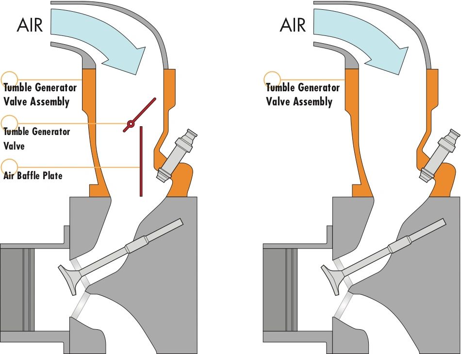
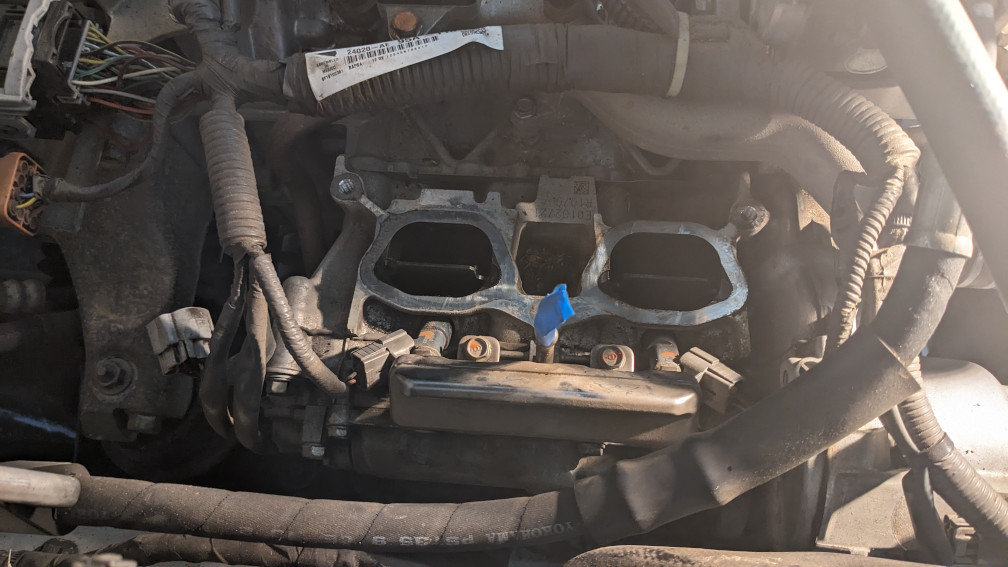
Why do I need a TGV? During a cold start the fuel has a harder time atomizing due to the lower temperature and low mass flow rate at idle. So when you start the engine cold the TGV will be closed. In the photo below, on the FB25 engine, the valve would close towards the inside of the engine, and air would flow through the bypass on the outer wall.
This lower cross sectional area should increase the velocity of what air is allowed into the head, and the abrupt increase in cross sectional area behind the valve should cause swirl. This is supposed to create turbulent flow, mix the fuel into the air more efficiently, and decrease emissions. Once your engine warms up, my understanding is that the TGV opens completely (straight up and down on the FB25) and remains that way until your next cold start.
What was wrong with my TGV? Nothing, from what I can tell. It had built up its fair share of carbon from the EGR/PCV just like everything else downstream. I removed and tested both valve bodies. One worked fine and the other wouldn’t move. I cleaned it up a bit with carb/choke cleaner, a toothbrush, and some paint thinner and it all worked great.
The fix
Ok, so you want to get at your TGV(s) on your FB25B engine. How do we actually do this? The service manual is actually pretty accurate, if you have a copy.
- Get the car into somewhere where you can keep it clean. This will probably take a full day if you’re doing it for the first time. It took me ~10 hours. (Including valve cover gaskets “since I was already in there…”)
- Relieve pressure from your fuel system. You will have to disconnect the input and return of the fuel rails. You do NOT want 50psi gasoline spraying into your eyes.
- Remove your glove box
- Remove the entire glove box surround, along with long skinny trim piece on top, and triangular trim against the passenger door.
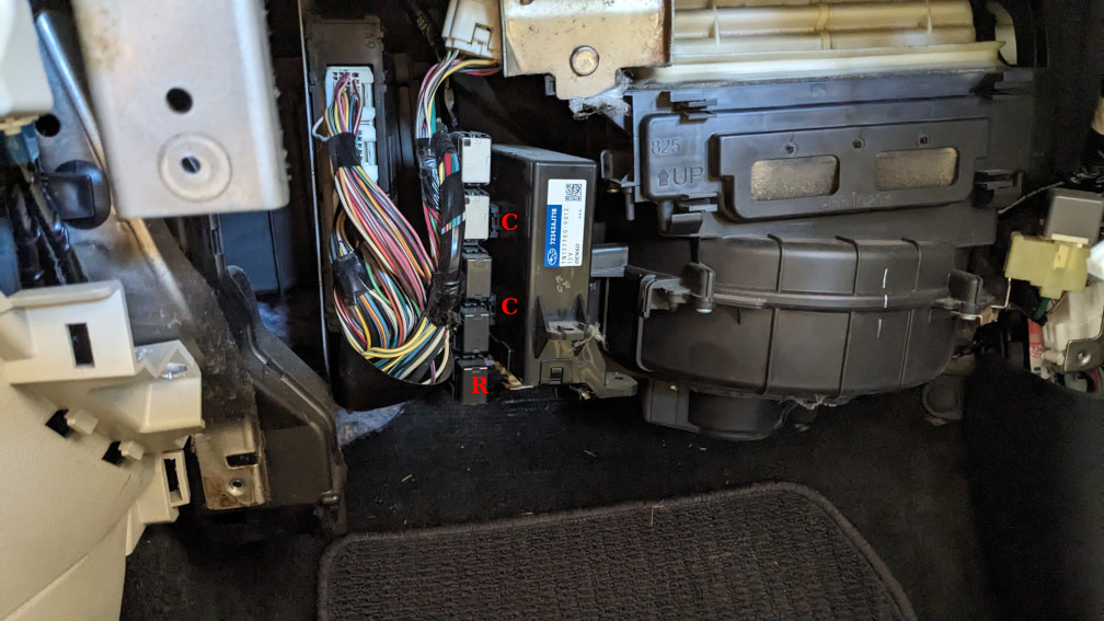
- Unclip the 5x relays from the side of the electrical box
- Remove the fuel pump relay, the bottom one
- Turn on the car and run it until it dies. Try to start it once or twice more to make sure you got it as evacuated as you can
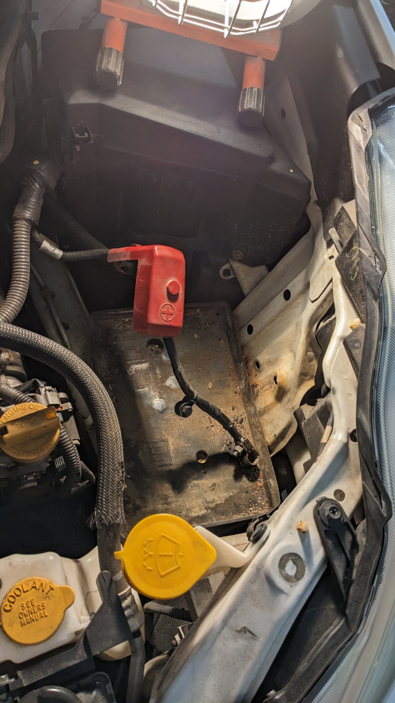
- Remove the negative battery terminal. I preferred to remove the entire battery to have more room.
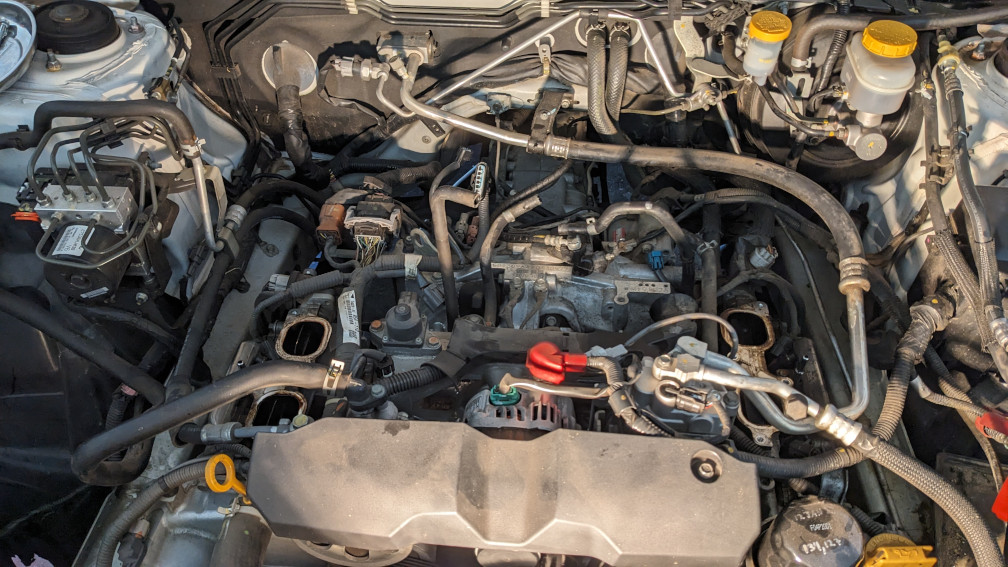
- Remove the intake duct and resonator. I preferred to remove the entire intake to have more room.
- Remove the intake plenum
- Loosen hose clamps and hoses from the throttle body
- Remove the steel u-shaped tube below the throttle body (unsure if it’s PCV or EGR)
- Remove 2x bolts on each of the runners
- Lift the plenum up slightly. The PCV/EGR tube curves upwards after entering the bottom of the plenum, so rotating the plenum backwards should allow you to slide it over that protrusion. You can remove two additional bolts on the bottom of that tube, where it exits the block, but those nuts are very hard to get back on without small hands and lots of extensions.
- Now that you can get underneath the plenum, unclip the feed and return lines using a pick. Also disconnect them from the short fuel rail on each bank.
- I would recommend removing the throttle body on a bench, and cleaning out the intake plenum (remove the MAP/etc. first). But this is optional.
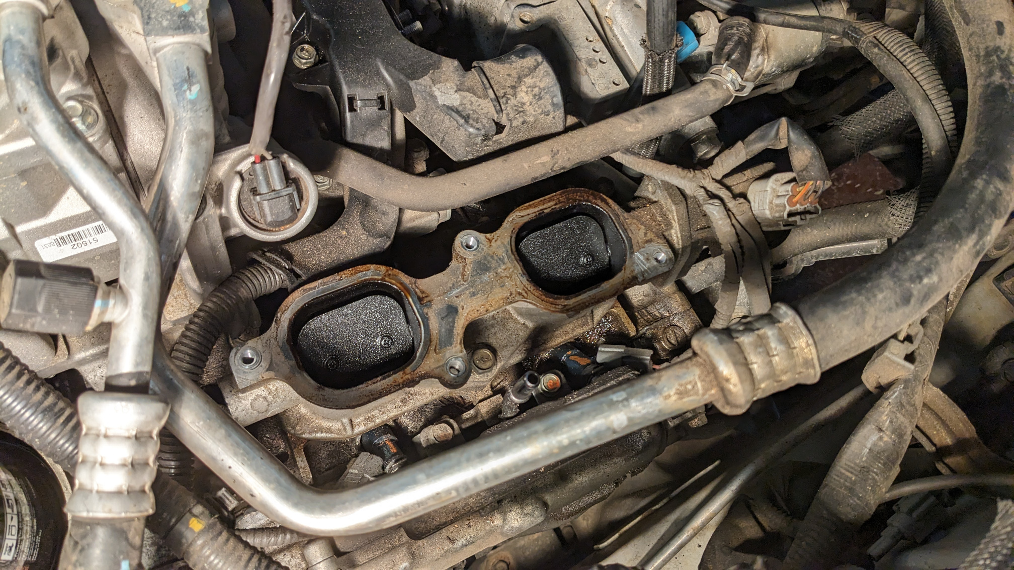
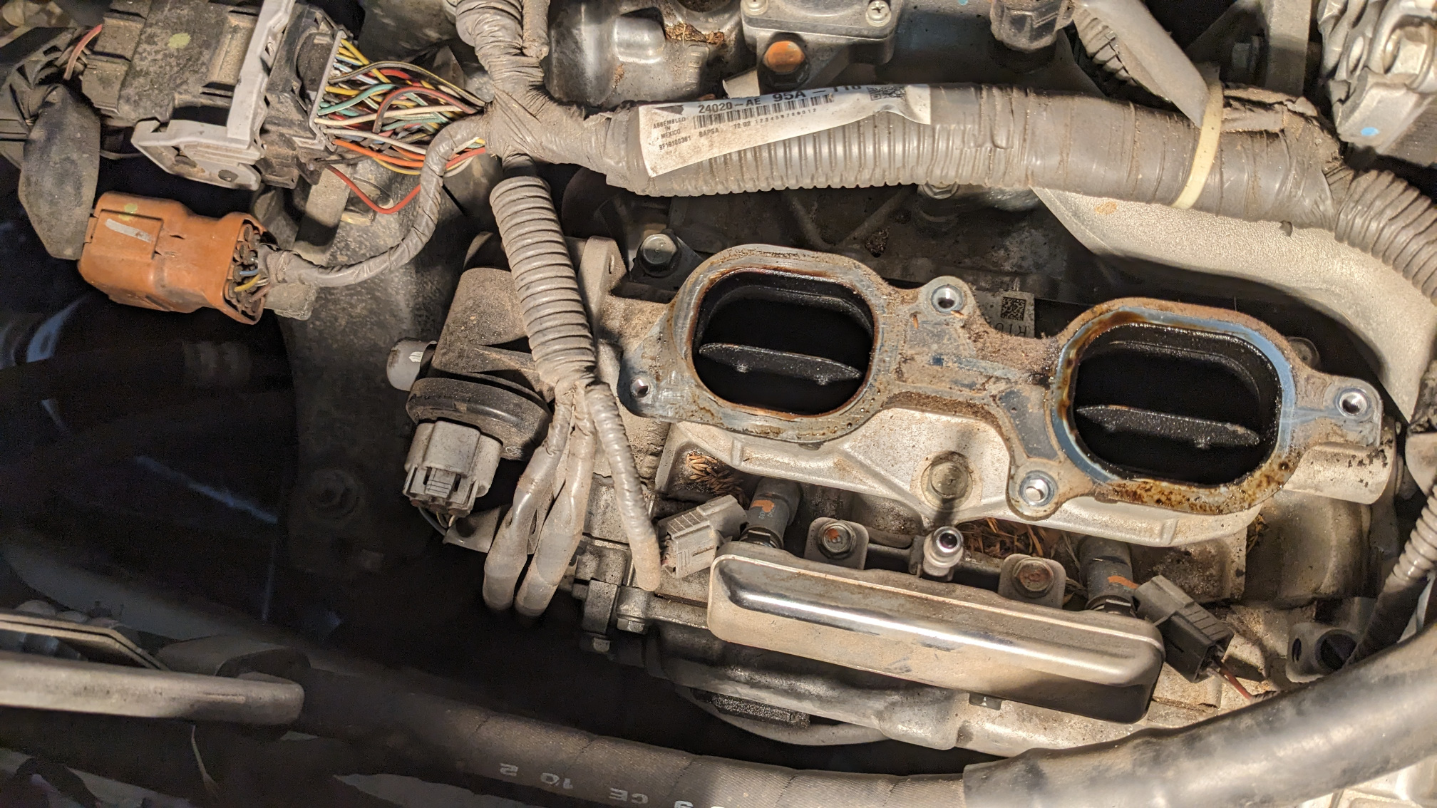
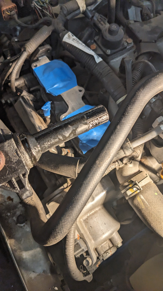
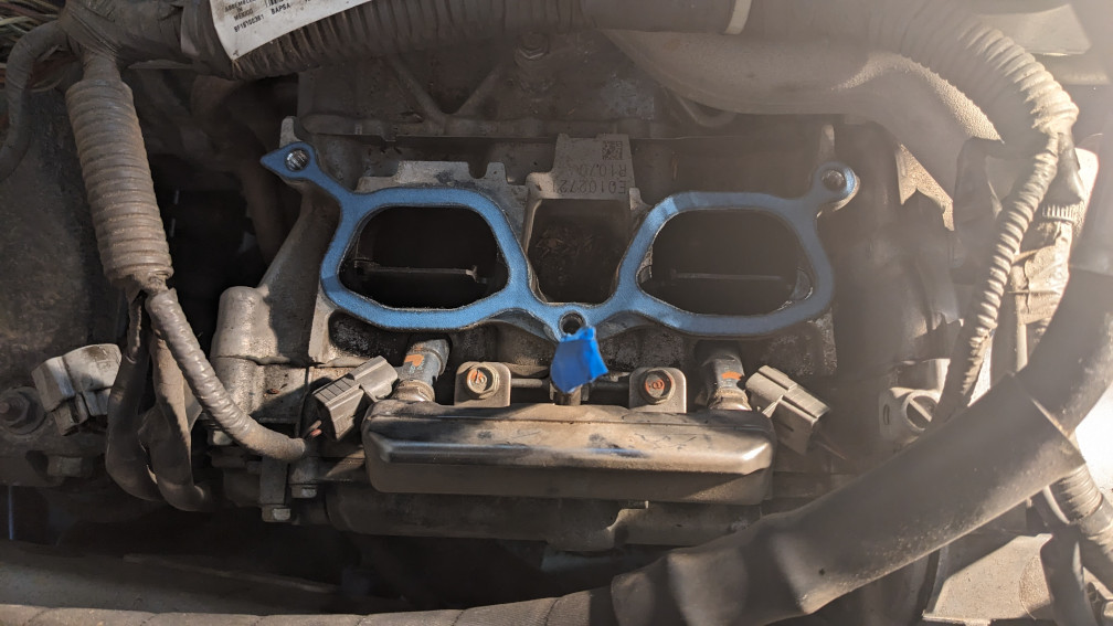
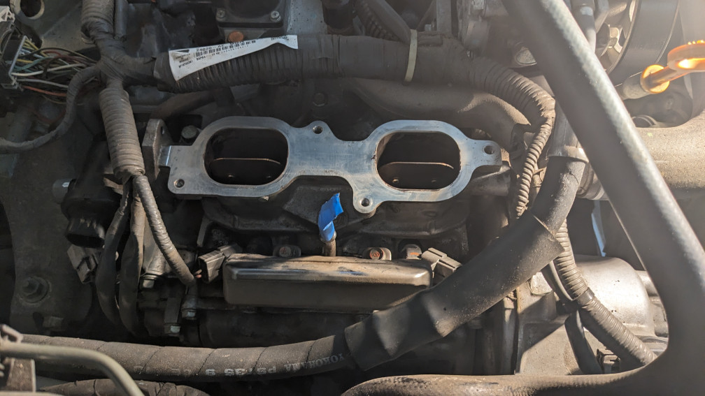
- Remove the TGVs. There are only three bolts on each holding them to the head.
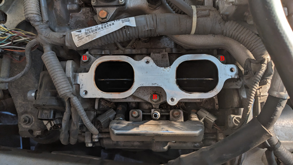
- Remove the gasket from the head, and block them off to prevent debris from falling in while working. I used carb and choke cleaner on a shop towel, wiping gently from the port to the outside edge of the head. Once complete, I covered them with some painter’s tape.
- Test the TGVs
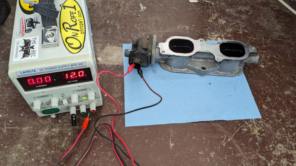
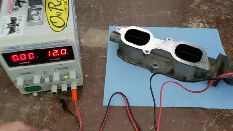
- The service manual has the pinout for the connectors. Picture to be added, but there are 5 pins. 3 on the top row, 2 on the bottom. They are centered horizontally, so they’re in a W configuration. The pins on the bottom are 4 and 5, and drive the motor.
- Hook up some alligator clips (or female spade connectors if you have some small enough) to each. Make sure you’ve got insulation and aren’t shorting against other pins.
- *Warning – You are only supposed to apply voltage to the motor for 10 seconds or less, or you risk burning up the windings. *
- Apply 12V DC across the pins. It will either move or stay where it is, depending on polarity and starting position.
- Reverse the polarity, the vanes should move 90 degrees.
- Reverse the polarity again for good measure (if there was no movement the first time), it should move again, back to the starting orientation.
- (optional) Remove the servo motor if it’s locked up.
- I set mine on a wooden workbench and used a wood clamp (with rubber pads to avoid digging into the aluminum) to hold it down.
- Use a phillips #3 (bigger than normal) screwdriver to remove the two screws. Keep lots of pressure on them, they are torqued well.
- There is nothing further in that looks serviceable. No springs/pins/etc. that would fall out
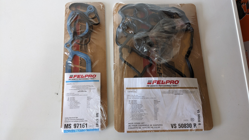
- Installation is the opposite order of teardown. I took this opportunity to replace the valve cover gasket and spark plug tube gaskets since I’m already in here and they’re a problem. But I won’t cover that here since it’s a pretty well documented process.
At this point I’m 2 months late posting this. But I’ve had no issues with any part of my intake since the fix. If anything stops working again, I think the solution is going to be to buy a set of used TGVs from a wrecked car on ebay, then replace just the servos. This shouldn’t require removing the intake, just pushing some hoses and wires out of the way.
Leave a Reply