Reverse Engineering our Minivan
2012 dodgegrand caravanthrottle bodyobd262TEPCMCAN busreverse engineering
5417 words. Read time: 24 Minutes, 37 Seconds
2025-09-02 15:00 +0000
Background
This past December our 2012 Dodge Grand Caravan died. We had a cold snap that hit most of the U.S. pretty hard. My wife parked it at home one afternoon, then it didn’t start back up. I troubleshot it a bit, but wasn’t able to get anything easy to work.
I ultimately decided to take it to a dealership close to us. It was a week or two before christmas, and they ended up not being able to get to it for 2 weeks. It turns out they had just been bought out by a company from Florida who was mismanaging things pretty spectacularly. The tow truck driver said they had lost over 80% of their techs, and he didn’t recognize anyone there anymore.
I ultimately just took it home and gave up for a bit. My wife needed a reliable car quickly, and this one had almost 300k miles on the clock. We bought her a new Subaru Forester, which is a great car so far.
It sat for even longer, I finally took it to a different dealership to at least do some electrical diagnostic work. Stellantis (Dodge, Chrysler, Ram, Jeep, etc.) is well known in the industry for locking down everything that they can, and it’s near impossible to find any proprietary information of use on the internet. So an hour or two with their diagnostic tools could save me a few days of headaches.
Eventually, that dealership also showed their ass, and I lost faith in their ability to provide any meaningful help. I was able to get it all back together and running just like it used to for pretty cheap. So I’m going to share my diagnostic process to hopefully help someone else in the future.
Applicability
Again, this is for a 2012 Dodge Grand Caravan SE, VIN 2C4RDGDG9CR2xxxxx. This falls into the 5th generation, which encompasses 2008-2018. This one is a 3.6 liter Pentastar V6 (flex fuel capable), with 62TE transmission.
This particular van is electronic throttle control (ETC) a.k.a “drive by wire”. I think the 2008-2010 are driven by a throttle cable, so some of this isn’t applicable. But a lot of the engine and transmission are the same, so most of this should apply broadly to many years.
It also applies to the Chrysler Town & Country, which is essentially the exact same system with a different look. As well as some Dodge Ram 1500 trucks that have this engine/transmission.
Troubleshooting Process
1: December 2024, Initial failure, transmission?
The car was shut down and didn’t restart. I had a no start no crank condition. It was frigid outside, and the battery was about 4 years old. So I took the battery into the house and trickle charged it for a few days. The battery was something like 8 volts when I initially checked. So I thought it was just causing some strange voltages in the computer systems, causing problems with logic gates.
The charged battery went back in, and it was the same problem.
Symptoms:
- No crank. Not even a click from the starter relay.
- No gear selection shown on the dash (PRND on this car).
- Security light blinking on the dash.
- Scan tool not communicating with PCM.
We had one key fob that died, and was out of sync with the car (won’t lock/unlock anymore). So I thought this was the extent security problem after a super dead battery.
I put the park brake on, and manually cycled the shift lever through its range. No change in gear selection on the dash. The options didn’t even light up.
In this vehicle, there are two gear select inputs. One from the shift lever on the dash, and another from the transmission. Unfortunately, the gear select mechanism on this transmission is inside the transmission, not on the outside like lots of other [well designed] vehicles.
The trans fluid needed to be changed anyways, since it was old and slightly burnt. So I checked the pinout of the transmission wiring harness connector and didn’t see the results that I was expecting. There are four pins that go to the transmission range sensor (TRS)
![]()
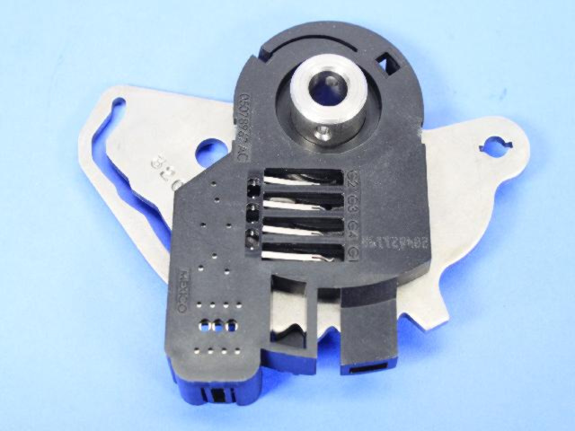 And here’s what the actual TRS looks like. Just a laser cut piece of steel with a plastic mask, carrier, and some wipers. Courtesy of MOPAR parts website.
note These are in reference to ground, which the TRS itself gets by being bolted to the transmission body. As you see on the image above, test all trans pins against the 12V reference except the list given, which includes these four pins.
| Pin Name / TRS Harness/ Trans Harness | T41 / C1 (Blk) / 5 (Ylw/DkBlu) | T42 / C2 (Gry) / 8 (DkGrn/Ylw) | T3 / C3 (Red) / 9 (DkGrn/DkBlu) | T1 / C4 (Ylw) / 13 (DkGrn/LtBlu) |
|---|---|---|---|---|
| Park | Closed | Closed | Closed | Open |
| Reverse | Open | Closed | Open | Open |
| Neutral | Closed | Closed | Open | Closed |
| Drive | Open | Open | Open | Closed |
| 3 (n/a this vehicle) | Open | Open | Closed | Open |
| Low (n/a this vehicle) | Open | Closed | Closed | Closed |
This part was a pain. I removed the front and lower pans off of the transmission to drain the fluid. You could get away with just removing the front, but the TRS is connected to the shifter shaft with a small roll pin. And it’s kind of hard to reach everywhere you need to. I didn’t get the roll pin aligned just right at first, dropped it into the trans, and had to retrieve it with a magnet. Just drop the bottom pan as well, you’ll be able to get your hands onto the TRS from both sides at once, and you’re already draining all the fluid…
In hindsight this was not necessary. There are selections on the TRS that are not used in this vehicle, and the offset threw me off. I already had the original TRS pulled out in order to see that it was good, and at that point it was just as easy to install the new one. It was something like $55, and I guess I’ll call that cheap insurance (these don’t wear out, they just don’t. There’s a reason they’re hardly ever replaced).
Anyways, I cleaned up the sealing surfaces, put on a new gasket, and torqued the pans back down to spec (a few lb*ft)
2: January 2025, works fine intermittently
The van worked again. I don’t know why. I just tried it randomly one day, and it started. I moved it around the driveway, and turned it off. Went inside to grab some things and take it on a test drive, and it wouldn’t start again.
The security light was taunting me… again. At this point it sat for a few months because I just threw in the towel and decided to focus my energy on other things (building a shed).
3: June 2025, cutting sling load, checking CAN traffic
We need to sell this thing and be done with it. The initial plan was to hold onto it until the youngest is ready to drive in ~18 months. But after sitting for just a few months, it smelled like mouse pee. They had gotten into the engine bay, and made a nest on the cabin air filter. They also chewed through the intake air temperature sensor wires. So I’m determined now to fix this problem before it gets to the point where it can’t be remediated.
I ran into some strange issues where I would try and open the side sliding doors and rear hatch, both with the key fob and with the buttons inside the van. They didn’t respond, and the gauge cluster informed me that I needed to be in Park or Neutral before I could open doors that way. I spent some more time checking pins on the shift lever and transmission harness, but didn’t come across anything conclusive.
I pulled the chewed wires and cut/stripped/crimped/shrink tubed them. The engine bay got cleaned out with bleach and a pressure washer. The cabin air filter got pulled. I gloved-up, pulled the cabin air fan and wiped out everywhere with more bleach. I even pulled the wiper arms and windshield cowl to get down in there where the air is supplied from outside.
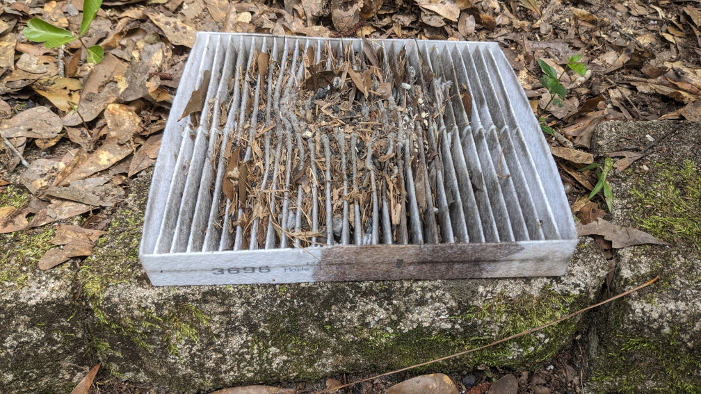 The rodents have made this their home.
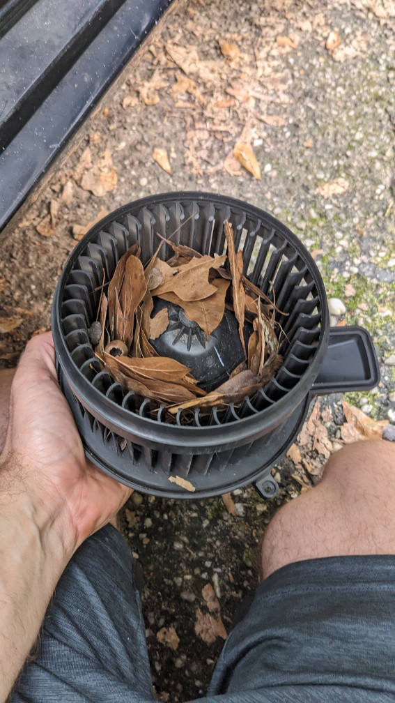 Even after evicting them, there were so many leaves that they fell down into the fan assembly. So I got to clean that out as well.
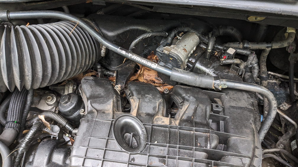 Where they were living in the engine bay, under the decorative cover and on top of the intake manifold.
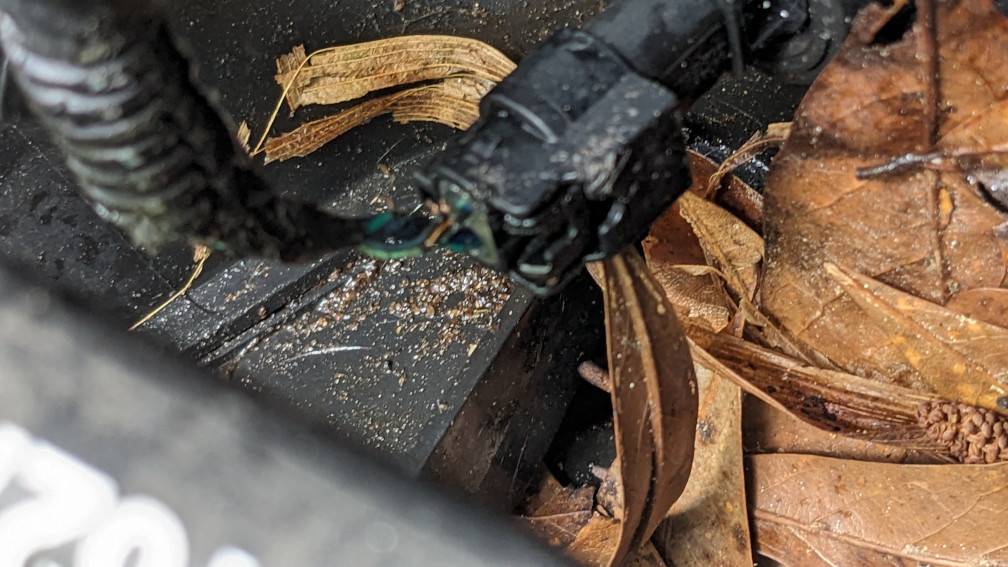 Intake air temperature sensor chewed almost all the way through.
The van started and ran. We took two of the kids to guitar practice across town. The middle child and I drove around for 45 minutes while the other one was in their lesson, so it got used for about an hour straight. It worked beautifully. A few days later I ran to Walmart to grab a few things, to include a new cabin air filter, and a carwash so I could take pictures to sell it. It wouldn’t start in the parking lot when I tried to leave. I called the oldest child, who came with his car and jumped me. I made it home, and just didn’t turn it off when getting gas, etc. A few days later, it wouldn’t start again.
I learned at this point how the starting system works. The Wireless IgNition (WIN) module is on the same CAN bus as the PCM. It has two antennas on it. One right on the [relatively small] module that communicates at low power with the key when it’s in the ignition. It also has a coaxial connector that runs up into the dash, and connects to a bigger antenna near the windshield. This is for when the key fob is further away. Either way…
The process as I understand it:
- The WIN module either has the key physically turned to accessory/on positions, or receives the appropriate start signal from a key if you have remote start ability.
- The WIN is connected to the shift lever near the steering column, and checks that you’re in Park or Neutral.
- The WIN communicates with the key to receive a rolling code and validate you aren’t a thief.
- The WIN communicates on CAN bus __ with the PCM, and checks the rolling code against the table that’s also in the PCM.
- If all is well, the PCM communicates to the gauge assembly (through the TIPM, where 3 CAN busses meet), and the security light turns off.
- The PCM checks a few other things, like pedal position, gear selection in the transmission itself, voltages on sensors. E.g. if you’re starting remotely, we check that the doors are all locked so a thief can’t just jump into the running car and try to drive off. If all is well, we continue.
- The PCM turns the engine on. Not entirely sure on the details, since there’s a lot going on here. The ignition coils, sensors, pedal, and throttle body are all connected directly to the PCM. I think there’s more CAN communication with the TIPM, and the TIPM is what closes the starter relay.
The astute amongst us realizes now that if the PCM is having trouble communicating, and the TRS is good, the car won’t know what gear its in, and won’t start (or display the correct gear on the gauge cluster). So don’t do what I did and fire the parts cannon at the transmission first, even it it is only ~$50. If I knew at the time what the CAN bus topology looked like, maybe I would have come to the correct conclusion; the TRS was likely just fine, and it just wasn’t getting the correct information all the way to the gauge cluster, because it needed to go through the PCM first.
Here’s a CAN bus topology that I took from Mr. Eric O. on the South Main Auto youtube channel, as he was troubleshooting a different Dodge minivan.
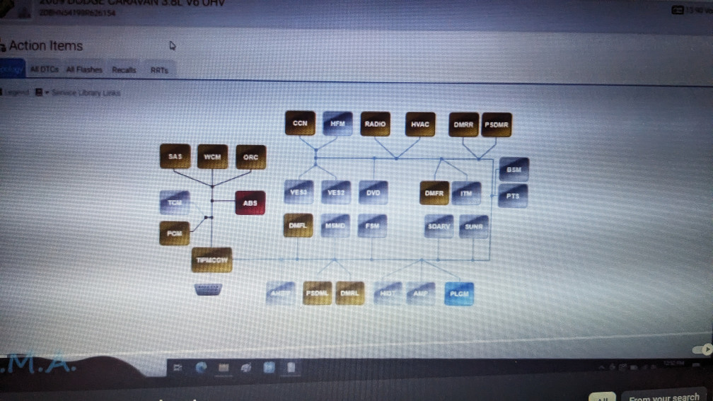
At this point I’ve started looking at new and refurbished TIPM and PCMs. It could be the PCM, or since everything goes through the TIPM (and they are notorious for failing in hidden relays soldered onto the board itself. Fuck you again Stellantis!) it could be failing to route CAN traffic between the three CAN networks in this car.
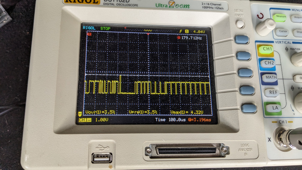
Here’s just the CAN Low line that I pulled from the WIN module. It looked fine on the oscilloscope. I also used a CAN bus USB-C board and SavvyCAN, and can read messages just fine. If it were bad, I would expect to see lots of noise, or slow rise/fall times. But all the lines were nice and crisp, quick rise times - near vertical, very little overshoot, etc.
The next step was to plug the WIN back in, and try again. At this point, there are other devices on the same CAN bus that could be ruining the signal integrity. But I didn’t see any of that. So it looks like the CAN network overall is “healthy” at the physical level.
4: July 2025, giving up and sending to the dealership
I took it to a different Dodge dealership not long after on a dolly with my truck. I told them I just wanted them to troubleshoot the car and tell me with certainty what module was bad. The electrical technician came out and talked to me to hear what I had done so far. They were a little appalled that the dash was torn apart, and that the fender liner was pulled. But I told them that I had to get in there to sniff the CAN lines, and that it would save them time getting to what they needed.
He agreed (after making jokes about me being an engineer, which technicians so often love to make), and within a week they had gotten to my vehicle in the queue and told me that the PCM was fried. No communication on any of the lines in/out, no indication that it was even powering up. My assumption is that a MOSFET in a power circuit inside there finally burned out. I still have the old one, so maybe someday soon I’ll pull it apart now that I have nothing to lose.
Long story short, they offered to sell me a new OEM PCM for $1900. I told them to pound sand, since the car is only worth like $4k in good condition at this point, and I intend to get rid of it.
I ended up buying a refurbished unit from MAKS ECM rebuilders for $170 or so. I provided them with my VIN when ordering, and it showed up within 4-5 days with decent instructions.
5: Still July 2025, losing faith in the dealership
I delivered the new PCM to the dealership, and they installed it. The car was non-mobile at this point, and I don’t think they wanted me to install it myself inside their shop or parking lot (because they like to make money of liability reasons). So I just let them do it. Unfortunately, they called a few days afterwards and said that I still had a lot of fault codes present.
Symptoms:
- Security light gone.
- Gear indicator was back on the dash.
- Car cranks, but no start.
- No 5V reference on multiple sensors.
They told me that the PCM that I bought was a piece of junk. That they are seeing lately that only about 25% of the customer provided units are working. And that their OEM unit is the only reliable solution. I told them I’d call the refurbisher and see about troubleshooting with them, or getting a replacement. My engineer spidey sense was tingling at this point.
I came in to the dealership on a Thursday afternoon after finding some rudimentary wiring diagrams earlier in the week and doing some thinking. There are splices in the wiring harness, and multiple sensors share ground and 5V reference, for obvious reasons.
If you’ve ever done failure analysis, you’re probably familiar with a fishbone diagram. During this process, I’m just thinking that if the CranKshaft Position sensor (CKP) only has 2.9 volts present, it could be any number of things:
- The PCM isn’t providing 5V reference.
- The PCM connector has a short between pins.
- The wiring harness has a short between wires somewhere where it’s rubbed through insulation.
- The wiring harness has a splice that is coming apart from 290k miles of vibration.
- The CKP is bad, and has an internal short causing voltage drop.
- A different sensor on the same 5V rail has an internal short, bringing all the sensors’ V_ref down on that circuit.
So I spoke with the technician and just asked questions about his troubleshooting process to see if I could trust him to make forward progress that I deemed worthy of $225/hr.
-
Did you bench test the PCM before installing it?
-
“No. That’s impossible”
-
Me thinking to myself: How did the people that refurbished the unit test it before sending it out? Their margins aren’t very large, if they have a failure that gets missed, shipping alone on a replacement probably eats all of their profit. So they must have a test bench and a procedure that’s thorough…
-
Did you unplug all sensors sharing a 5V reference, and check continuity on ground and 5V pins? Did you check for shorts to ground with all sensors disconnected?
-
“No.”
-
How did you check for 5V?
-
“I unplugged the manifold air pressure (MAP) sensor and tested there, and saw less than 3V. I also unplugged one of the camshaft position sensors and saw the same thing.”
He mentioned the CKP specifically on the phone call earlier in the week, then admitted that he never touched that sensor (it’s kind of buried down low on the engine block and usually pretty dirty). So his “low CKP voltage” must be based solely on a fault code showing on the scan tool, not good diagnosis work.
So at this point I know that he hasn’t been thorough. They’ve charged me 3 hours of work to plug in 2 connectors to the PCM, and tighten the 3 bolts that hold it to the frame. Then he unplugged the two sensors that are easiest to get to on the top of the engine, but tried nothing else. These fuckers are charging $225/hr for shop labor, and making a huge profit (I checked glassdoor, a Dodge electrical technician with 15+ years of experience makes ~$35/hr).
I’ve heard a few times that Stellantis dealerships don’t hire good technicians, and good technicians usually refuse to work on garbage. I thought it was funny at the time, but am learning the hard way that most stereotypes are rooted in some truth.
6: August 2025, doing it my damn self
I got the van back home. I paid for a tow truck this time. I was going to do it myself with my truck and a dolly from Uhaul, but my truck’s starter relay died right before I was supposed to go pick it up. It was the hottest that it got this summer, and I was glad to have a driver with a winch and flatbed when it was 110F at 3pm that day (maybe one of the reasons the starter relay on the truck started sticking when it’s usually rock solid). $135 wasn’t too bad, considering the time and pain it was saving me on that particular day. And the driver was a good dude that I enjoyed talking to.
I tried the local library, and they no longer have a subscription to Chilton’s online database (the one with excruciating details, beyond what are in their cheap-ish paper manuals). Apparently not enough people were using it to make the $1300+/yr subscription worth it.
I have the Haynes manual for the car, and it doesn’t get to this level of detail. For anything transmission-related it just tells you that “this is beyond the capabilities of a DIY owner, take it to a shop”.
I thought about buying a bidirectional scan tool. Even the cheap ones are $4-600, and the used ones have expired licenses that aren’t super useful sometimes unless you drop some serious money on a license renewal, at which point it’s better to just get a new one from a cheaper brand that has 3 years included.
Ultimately I made an account on justanswer.com. It was $5 to make an account, and $40/mo for unlimited questions. They put me into a chat with a technician, and within 5 minutes he had pulled the engine wiring diagram and sent me a .pdf of it. Then he gave me his username, so if I had additional questions during the rest of the process, I could get linked back up with him instead of a new person with no history. You have to remember to cancel the subscription, but overall $45 was pretty cheap to get the diagram that I got.
I found an additional piece of wiring that had been chewed by mice under the upper intake manifold, not even that far down into the engine. Once that was done I hard reset the PCM. This involved unhooking both positive and negative battery cables, connecting them together, and letting all capacitors drain for at least 10 minutes. You can also turn the key to the on position for a bit and help the caps drain faster. Then clear all codes with a scan tool before starting the engine, just in case an active fault changes the behavior of the PCM.
7: End of August 2025, final piece of the puzzle
Hook it back up, and give it a shot. It took a little while to crank, but eventually started. It ran rough at first as I think it re-learned the fuel trims it needed on the injectors, but eventually idled just fine. The problem now is that I stepped on the throttle and nothing happened. It would only idle. I could move it around the driveway thankfully, but I’m not getting on the road unless I’m trying to go 10mph or less with my hazards on.
If you have this problem, you’re no stranger to “the lightning bolt”, or the Electronic Throttle Control (ETC) light.

I just hooked up my little ELM327 bluetooth OBD2 adapter and used Torque on android (which is a fantastic app, albeit not well maintained anymore) to log some data. I was looking at throttle body position, and pedal position, and looking for problems.
The pedal has two potentiometers in it for redundancy, which means additional safety (if one signal cuts out, you have another one to check, and not go full throttle into a barrier on the interstate). So there are two PIDs, accelerator pedal D and pedal E. One is roughly half of what the other is.
The voltage on one signal cut down to 0 for a single frame intermittently. It happened around 30% of travel, so I thought that it was a potentiometer wiper cutting out on a single wrap that was worn more than the others. It turns out, this is probably built into firmware of the microcontroller in the pedal. It will periodically cut down to 0V as a kind of heartbeat for both the PCM and for a human troubleshooting.

I went to a junkyard down the road and bought a used pedal and throttle body just in case. I installed the pedal, same problem. No throttle response at all. I installed the throttle body as well, same problem.
I tried to do a pedal re-learn
- Turn key to ON
- Wait 10 seconds
- Push pedal all the way to the floor (some people say to ramp up slowly) and hold for 10 seconds
- Let pressure off the pedal (some say to do it slowly on the way down as well)
- Wait 10 more seconds
- Turn key to OFF, and cycle back to ON
- Start the vehicle
Aaaaaand… same problem. I found out later that this procedure is programmed into the PCM for these vans 2013 and newer. And that for 2012 and earlier, you need to command the PCM to do a re-learn procedure. So we’re back to the question of buying a bi-directional scan tool, renting one for a day, hiring a mobile mechanic, or taking it back to the same dealer who already overcharged me.
I found Windows/Android software called AlfaOBD. It works for most things with a regular old cheap ELM based bluetooth OBD2 scanner. It is specifically for Stellantis vehicles (who own Alfa Romeo, which I think is where the name comes from). It was $49 for a permanent license on android, and if you also want it on the other platform, they’ll give you a discount on whichever one you’re missing.
So I did that, and re-learned the pedal positions. It was simple, albeit a little hard to navigate the app initially. It’s not a very intuitive interface, but if you look around and click buttons for a minute you can find everything you need. Once complete the van finally worked as intended.
I uninstalled the new-to-me pedal and throttle body, put back my original items, and re-learned again to be safe. The original equipment worked fine, and I brought it back to the u-pull-it yard for a full refund.
8: Appendices
If you’re in the same boat, it’s kind of hard to determine what the actual problem. I found numerous resources online (on justanswer.com, with actual technicians) telling folks that their throttle body must be bad, and need to be replaced. So the guy goes and buys a new throttle body, potentially an OEM new unit for $500+, and still has the ETC light. Then asks the tech what to do now, and presumably he got ghosted.
Throttle Body
Pinout:
| Pin | Color | Diagram Name | Real Name | Notes |
|---|---|---|---|---|
| 1 | DkBlu/Gry | MTR POS CTRL | Motor + | |
| 2 | DkBlu/LtGrn | TP MTR NEG CTRL | Motor - | Not bonded to the aluminum body |
| 3 | Brn/DkGrn | TP SNSR SIG 2 | Throttle Position #2 | 0V when closed, 5V when open |
| 4 | Brn/Org | PRIM SNSR FD 1 | Vcc (5V supply) | |
| 5 | Brn/Gry | TP SNSR SIG 1 | Throttle Position #1 | 5V when closed, 0V when open |
| 6 | Brn/DkBlu | TP SNSR RTN | Ground | Not necessarily grounded to the frame |
-
Check for continuity between pins 1 and 2. This is just the motor winding. I got 33.4 kOhm when I tested mine.
-
Check voltage on pins 3 and 5. I checked resistance with nothing attached, and didn’t get anything meaningful. I.e. my multimeter showed the resistance high enough that it called it NC (no connection). But with power (Pin 6 -Ground, Pin 4 - 5V) applied, you will see between 0 and 5 volts. Pins 3 and 5 will have opposite readings, and always sum to 5V total between them. You can just push it with your hands, as long as you don’t let it pinch your finger (the spring is fairly stiff).
-
Test if the motor turns the butterfly valve when given power. I measured the motor driver circuit pushing just a few volts to these pins. Approximately 1.8V, fluctuating at around 60Hz. When hooked up to 5V on my power supply, it dropped down to something like 2V and 1.7A. So don’t power it off of a 12V battery or you risk burning it out. But you can connect to 5V directly for a few seconds, and it should open all the way.
-
Test it all together. If you have an oscilloscope, or a multimeter that updates fairly quickly, you can power the motor and watch the two potentiometers alternate in real time. I tried to drive this with an Arduino Motor Shield V3, but it didn’t really have the power to push this motor reliably. I ended up using a little controller board for a 2 or 3 pin computer fan, just feeding it 5V instead of 12V, and it actually did pretty well and didn’t overheat. The arduino motor shield, even with a heatsink I added, nearly let the smoke out of the H-bridge chip once.
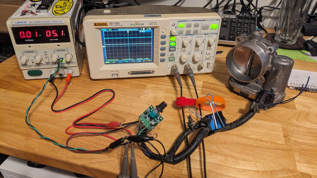 Here’s how I had everything connected. 5V on the power supply feeding everything. One 5V feed going into the fan PWM controller board, then into the throttle body motor. The other powering the potentiometers. Then one probe connected to each of the signal outputs, with a nice long sweep time to show the movement on the screen easily.
And here’s a short video of what it all looked like in motion.
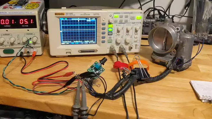
There’s quite a bit of lag between me twisting the knob, the butterfly valve actually rotating, and the voltages updating on the scope screen. But hopefully you can see me twisting back and forth, and see the two outputs fluctuating in reverse of one another to demonstrate my point.
Pedal
The accelerator pedal is a much more simple device. It has 6 pins, which you can see on the wiring diagram linked below.
Pinout:
| Pin | Color | Diagram Name | Real Name | Notes |
|---|---|---|---|---|
| 1 | Brn/Org | POSTN 1 SNSR FD | 5V | |
| 2 | Brn/Gry | POSTN 1 SNSR SIG | Signal 1 | Potentiometer, 0V when idling |
| 3 | Brn/DkGrn | POSTN SNSR RTN | Ground | |
| 4 | Brn/Vio | POSTN SNSR RTN 2 | Ground | |
| 5 | Wht/Brn | POSTN SNSR 2 SIG | Signal 2 | Potentiometer, 0V when idling |
| 6 | Vio/Gry | POSTN 2 SNSR FD | 5V |
So there are 2 sets of potentiometers. 5V, ground, and the return voltage to tell the PCM where in its travel the pedal is, for each set. The sets of pins are perfectly mirrored across the centerline of the plug, grounds in the center, Vcc on the ends.
The two are electrically isolated from one another. If you follow the wires on the diagram linked below, you’ll see that they all end up on the C1 connector of the PCM, three on pins 67-69, and the other three on pins 91-93. The voltage and signal go to one half, and the ground (return as they call it on the diagrams) goes to the other half. I’m not sure why this is split, since all 6 converge in connector C100 (a large grey connector anove the bell housing). It’s not like they’re taking different paths through the engine bay so that if one gets cut by a CV axle the other one will continue to work, but I digress…
I didn’t have luck just measuring ground-signal or 5V-signal to get a resistance. These are not simply passive components. I had to apply 5V across one set of pins before I could get a voltage output from the signal (on that half that I powered up). You should see one signal go to some voltage level between 0 and 5, and the other will only go 0-2.5. An oscilloscope is always a great tool to have, but an multimeter will work fine for this.
Links
Here are some useful links I’ve found along the way:
MOPAR connectors This site will show you what a connector looks like. Some are interconnects in the wiring harness like “C100”. Some you can look up by the specific sensor. It shows the connector shape, each pin number, wire color, wire gauge, and function name. It doesn’t really tell you what exactly you’re looking for on each wire, like “PWM signal at __ frequency”, “5V source”, “ground”, “serial data at logic level __”. But you can’t really find that data anywhere…
Wiring Diagram Modified with my own information, because there were some errors with wire colors being incorrect with what’s actually on the vehicle.
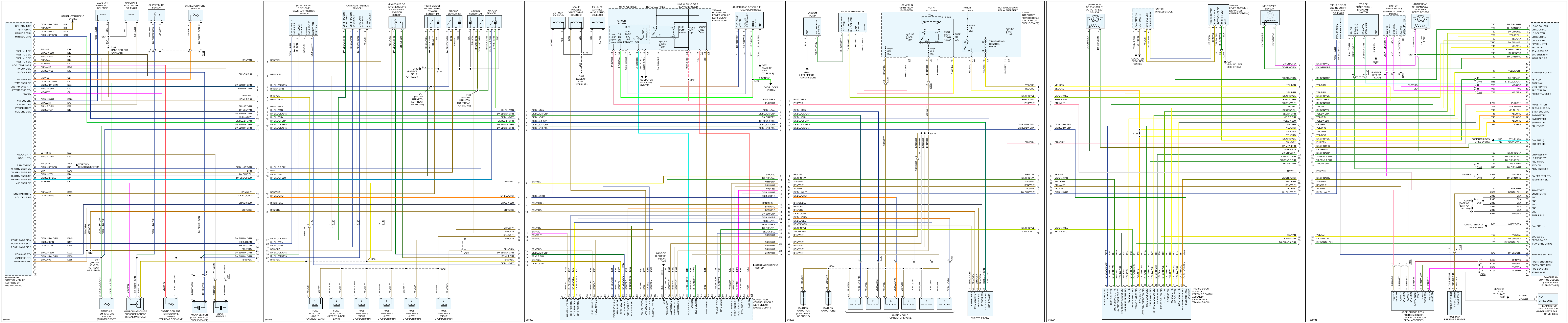
PCM Pinout From the first link. But easier to get to, with both C1 and C2 together. Since those are the only connectors on the PCM, so all wires on one document.
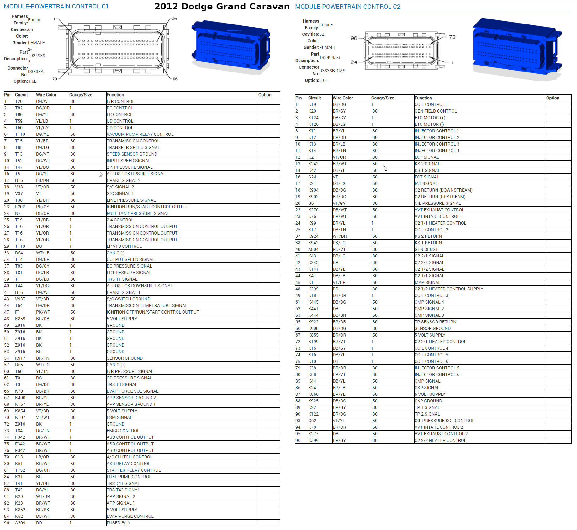
Transmission Information Quick reference for the 62TE transmission. Not all inclusive, but plenty of info for what we’re doing in the scope of this article. There is a Automatic Transmission Service Group (ATSG) technical bulletin as well with more info, but it’s not specific to this vehicle. So it shows C1/2/3/4 into the PCM, which isn’t correct. You can google for this and get it for free.
AlfaOBD Not much by way of tutorials, but everything was pretty easy to figure out. And there are probably forums somewhere (I never needed them to navigate the steps required for these fixes)
Subaru Outback 2014 Radiator Fan Troubleshooting For something else. Just checking if putting a link here allows the file to be served, or if the problem is something else.